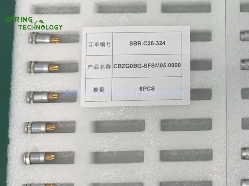


CBZG0BG-SFSM05-0000 Push-Pull Connector for Portable Battery Impedance Testers 2026: 0B 5-Contact M9 Panel Socket
The CBZG0BG-SFSM05-0000 push-pull connector is a five-contact 0B panel socket with nut fixing and an M9 panel mounting hole, specified for the auxiliary measurement interface of portable battery impedance testers — solder termination, push-pull self-latching coupling, IP50 when mated, a -45 °C to +125 °C range, 750 V working voltage and 6.5 A per contact on the 0.7 mm 305 insert, with more than 5,000 mating cycles. It is a signal and measurement interface, not a high-current battery terminal and not a substitute for the instrument’s Kelvin probes.
Battery condition monitoring is routine work in substations, data centres, telecom sites and industrial plants: float voltages are logged, impedance or internal resistance is trended, and weak cells are identified before a string fails. The tester does that with probes on the terminals and a handheld instrument in the technician’s other hand — which means the external interface gets plugged and unplugged at every cell, on ladders, in cable trays and inside cabinets.
Core answer: CBZG0BG-SFSM05-0000 gives that tester a fixed panel interface that stays on the enclosure while the measurement accessory is detachable: five low-voltage contacts on a 0.7 mm contact size, 750 V working voltage, 6.5 A per contact, ≤12.5 mΩ maximum contact resistance and a PPS insert, all rated IP50 when mated. The five contacts can carry auxiliary measurement signals, temperature feedback or accessory identification circuits, and the socket mates with a 0B straight plug carrying the same 305 five-contact insert.
1. Technical Parameters & Engineering Standards
Every value below for the CBZG0BG-SFSM05-0000 push-pull connector is taken from the published 0B platform documentation and from the 305 five-contact insert row of the product page P/N table for this socket. Items that depend on the order configuration are marked as such.
- Latching Mechanism: push-pull self-latching coupling — the mating plug seats with an axial push and releases by pulling the outer sleeve, with a keyed shell (key G, with A…M and R variants) so adjacent interfaces cannot be cross-mated.
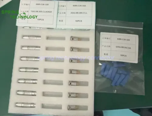
- Recommended Hardware: the ZGG.0B fixed socket on the enclosure and a TGG.0B straight plug on the measurement cable, both from the Spring Technology 0B range.
- Key Metric: 6.5 A per contact on the 0.7 mm 305 insert, ≤12.5 mΩ maximum contact resistance, 750 V working voltage, IP50 when mated and more than 5,000 mating cycles.
1.1 Configuration Summary
| Parameter | Value / Status |
|---|---|
| Model | CBZG0BG-SFSM05-0000 |
| Body | 0B fixed panel socket, female solder contacts, nut fixing |
| Contacts | 5 (305 insert) |
| Contact size | 0.7 mm |
| Conductor size | AWG 22–26 |
| Working voltage | 750 V |
| Rated current | 6.5 A per contact |
| Contact resistance | ≤12.5 mΩ |
| Termination | Solder |
| Mounting | Nut fixing through the enclosure wall; M9 panel mounting hole as specified for this order |
| Keying | Key G, with A…M and R variants available in the 0B range |
| Insert material | PPS (polyphenylene sulfite) |
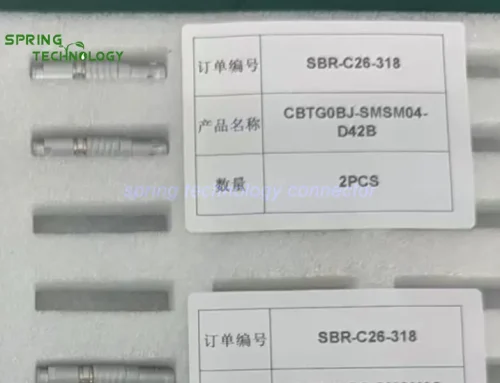
| Mating plug | 0B straight plug with the 305 five-contact insert — CBTG0BG-SMSM05-D52B in our catalogue |
| Protection index | IP50 when mated |
Note: the panel cutout, mounting orientation and mating plug should be confirmed against the product drawing before the enclosure is machined. The protection rating applies to the mated pair, not to the socket on its own.
1.2 Shared 0B Platform Specifications
| Parameter | Value |
|---|---|
| Shell size | 0B — layouts from 2 to 9 contacts |
| Operating temperature | -45 °C ~ +125 °C |
| Humidity | Up to 95% at 60 °C |
| Vibration resistance | 10–20,000 Hz, 15 g |
| Mechanical shock | 100 g · 6 ms |
| Salt spray corrosion test | >48 h |
| Mating cycles | >5,000 |
| Protection index | IP50 when mated |
| Termination | Solder |
| Fastening type | Push-pull |
| Shell material and finish | Brass, chrome plated |
| Contact material and finish | Brass, gold plated |
| Insert material | PPS (polyphenylene sulfite) |
| Cable opening | 1.5–5.5 mm across the 0B platform |
Note: these are platform-level values published for the 0B shell, so they describe the family the socket belongs to rather than a single supplied part. The finished instrument still has to be evaluated as a system.
2. Key Advantages of the CBZG0BG-SFSM05-0000 Push-Pull Connector
An external measurement interface on a handheld tester is judged by three things: whether it survives being connected at every cell, whether it can be serviced without opening the case, and whether it adds anything to the measurement uncertainty. The characteristics below explain why this CBZG0BG-SFSM05-0000 push-pull connector suits that job:
2.1 Five Contacts for Multiple Auxiliary Signals
The CBZG0BG-SFSM05-0000 push-pull connector carries five low-voltage contacts on a 0.7 mm contact size. In a portable battery impedance tester those are usually assigned to measurement feedback, a temperature sensor connection and an accessory identification circuit — enough to let one accessory connector carry several functions instead of adding separate interfaces to the enclosure.
The final contact assignment is the instrument designer’s decision; the connector provides the physical paths, not a fixed protocol.
2.2 Push-Pull Locking for Convenient Probe Connection
Technicians move from cell to cell and from string to string during an inspection, so the measurement accessory is connected and disconnected continuously. The plug mates with the CBZG0BG-SFSM05-0000 push-pull connector by an axial push and releases by pulling the outer sleeve, with no threaded collar to unwind while standing on a ladder.
The latch also resists the accidental pull that comes from a cable caught on a tray or a rack edge during handling, which is how external measurement interfaces usually get damaged.
2.3 Fixed Panel Mounting for Instrument Integration
CBZG0BG-SFSM05-0000 is a fixed panel socket with nut fixing and an M9 panel mounting hole. It gives the tester a defined external connection point: the internal harness stays inside the enclosure, the measurement cable is detachable, and no one has to open the instrument to swap an accessory.
That matters on a portable instrument because every opening disturbs the enclosure, its seals and the calibration access path. A serviceable external connector reduces the number of interventions over the life of the tester.
2.4 PPS Insulation for Reliable Contact Separation
The insert in the CBZG0BG-SFSM05-0000 push-pull connector is moulded in PPS (polyphenylene sulfite), the material specified across the 0B platform. It holds the five contacts at a fixed spacing and provides predictable insulation between adjacent circuits, which is what an auxiliary measurement interface carrying low-level signals from a temperature sensor or an identification circuit needs.
Stable contact positioning also matters for repeatability: a connector whose contacts shift under cable load adds variability to every measurement that passes through it.
2.5 Controlled Contact Resistance for Measurement Interfaces
For the CBZG0BG-SFSM05-0000 push-pull connector, the maximum contact resistance of the 305 insert is published as 12.5 mΩ. For a measurement accessory that figure matters because the connector sits in series with the signal path, and every milliohm in that path is one more term the instrument has to account for.
It does not make the connector a precision shunt. Accurate battery impedance testing still depends on the measurement method, the probe construction, calibration and compensation for cable and contact resistance — the connector’s contribution is bounded, not eliminated.
2.6 Shielding Performance When the Assembly Is Properly Built
The published specification for the mating plug side of the CBZG0BG-SFSM05-0000 push-pull connector lists a minimum shielding performance of 75 dB at 10 MHz and 40 dB at 1 GHz. In an instrument that injects a test signal and measures a small response, that attenuation is useful when the auxiliary harness runs beside switching supplies or inverter cabling.
The figure is a connector-level property. Real EMC performance depends on the cable shield, its termination at both ends, the grounding arrangement and the enclosure design.
2.7 Mechanical Endurance for Repeated Maintenance Operations
The CBZG0BG-SFSM05-0000 push-pull connector is specified for more than 5,000 mating cycles on the 0B platform. Battery testers are used at commissioning, during periodic inspection, in troubleshooting and in every subsequent maintenance visit, so the interface becomes a wear item long before the electronics do.
Sacrificial wear is exactly what a panel socket should offer: when it eventually wears, the socket can be replaced from outside the enclosure instead of the whole harness being re-terminated.
3. Why Choose the CBZG0BG-SFSM05-0000 for Battery Testing Equipment?
Portable battery impedance testers need practical interfaces for external probes and auxiliary measurement accessories: easy to operate, mechanically secure and suitable for a compact enclosure. The CBZG0BG-SFSM05-0000 push-pull connector offers the characteristics below:
The environments where these testers are used shape the requirement. In a substation the instrument is carried to a battery room and used on strings that are still in service; in a data centre the same tester works in a hot aisle with limited space for a cable entry; at a telecom site it is often operated by one technician on a ladder. In each case the external interface has to accept the accessory cable quickly, hold it while the probe is moved to the next cell, and let the accessory be replaced without disturbing the enclosure.
- Five low-voltage contacts for auxiliary signal connections.
- Push-pull locking for repeated accessory connection and replacement.
- Fixed panel mounting with an M9 mounting hole.
- PPS insulation for predictable contact separation.
- A published maximum contact resistance of 12.5 mΩ.
- Specified shielding performance when the harness is properly built.
- More than 5,000 mating cycles.
Three boundaries are worth stating plainly. First, this is not a high-current battery connection: it is a five-contact low-voltage interface rated 6.5 A per contact, and it does not replace the dedicated Kelvin probes or the battery-terminal clamps that carry the test current. Second, the protection rating is IP50 when mated, which suits indoor or protected environments and does not make the interface waterproof. Third, the contact resistance is a bounded contribution, not a measurement guarantee — the instrument’s compensation and calibration still decide the accuracy.
Before integration, engineers should verify the mating plug, the pin assignment, the measurement circuit, the cable shielding and grounding arrangement, and the environmental requirements of the finished instrument.
4. 0B Series Connector Family Overview
The 0B shell is the compact member of the 0B series: layouts from 2 to 9 contacts, solder termination, push-pull self-latching coupling, IP50 when mated and a -45 °C to +125 °C operating range. Portable instruments that need a smaller interface than the 1B shell but more contacts than the 00B family usually settle on this size.
4.1 Available Configurations
The five-contact 305 insert sits in the middle of the range: two and three contacts cover simple power and status circuits, six to nine contacts serve denser signal bundles. Plugs, panel sockets and free sockets share the same contact system, so an accessory interface can be built with a panel socket on the enclosure and a plug on the cable.
In the CBZG0BG-SFSM05-0000 push-pull connector arrangement, the socket is the fixed half and a 0B straight plug is the half that travels with the measurement cable — the arrangement that keeps the instrument sealed while the accessory stays replaceable.
4.2 Customization Services
Beyond the catalogue configurations, Spring Technology builds custom cable assemblies around the 0B platform for the CBZG0BG-SFSM05-0000 push-pull connector: conductor mapping to the instrument’s wiring schedule, shielding and screening choices, overmoulding or bend relief on the accessory cable, labelling and 100% continuity testing before shipment.
5. Frequently Asked Questions (FAQ)
Conclusion & Call to Action
The CBZG0BG-SFSM05-0000 push-pull connector gives a portable battery impedance tester a serviceable external measurement interface: five low-voltage contacts, pull-and-push operation, nut fixing with an M9 panel hole, a bounded contact resistance and a PPS insert rated over 5,000 mating cycles — while staying clearly on the low-voltage side of the test.
For more information about our 0B series connectors or to discuss your requirements, contact us at [email protected] or [email protected], or visit our website.
Designing a battery maintenance instrument? Send us your auxiliary signal count, panel cutout and accessory cable requirements — our engineering team will respond with a tailored connector proposal within 24 hours.
Further Reading
- 0B Precision Sensor Connector 2026: CBTG0BG-SMSM05-D52B Plug and CBZG0BG-SFSM05-0000 Socket for Load Cells and Accelerometers
- CBTG2BG Push-Pull Connector for Battery Module Charge-Discharge Testers 2026: 2B Series 8-Contact Connector
- CBZG0BG Push-Pull Connector for SF6 Dew Point Analyzers 2026: 0B 5-Contact Panel Socket
- CBZG0BG Push-Pull Connector for X-ray Residual Stress Analyzers 2026: 0B 5-Contact Panel Socket
- CBZG00BG Push-Pull Connector for Insulation Resistance Testers 2026: 00B Series 4-Contact M7 Panel Socket
- 0B Series Push-Pull Circular Connectors — Configurations, Specifications and Downloads
- ZGG.0B Fixed Socket — 0B Panel Socket Product Page
- Custom Cable Assembly Services — Measurement Accessory Harnesses