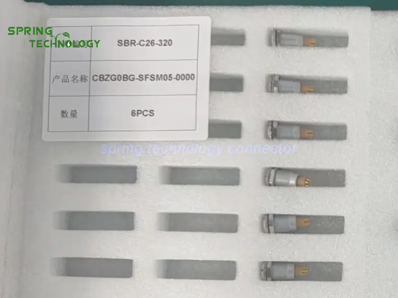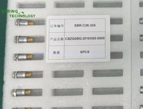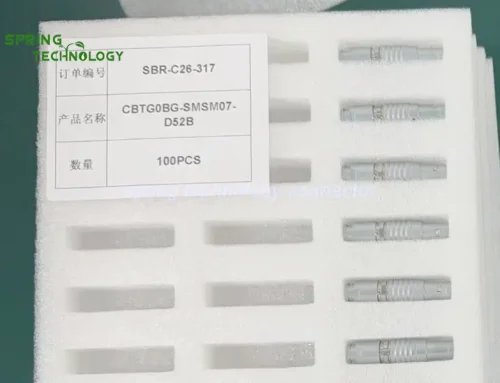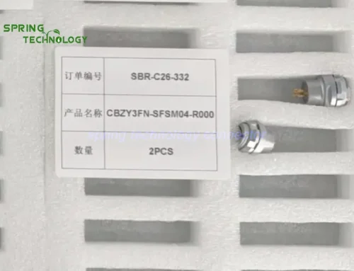


CBTG0BG-SMSM05 Push-Pull Connectors for Transformer Oil Breakdown Voltage Testers 2026: CBTG0BG-SMSM05-D52B Plug and CBZG0BG-SFSM05-0000 Panel Socket
The CBTG0BG-SMSM05 push-pull connectors pair a five-contact 0B cable plug with a nut-fixing panel socket, and can be evaluated for the auxiliary low-voltage interfaces of portable transformer oil breakdown voltage (BDV) testers — solder termination, push-pull self-latching coupling, IP50 when mated, a -45 °C to +125 °C range, 750 V working voltage and 6.5 A per contact on the 305 insert, and more than 5,000 mating cycles. They belong to the control and signal side of the instrument, not to the high-voltage test circuit that stresses the oil sample.
A BDV tester is a high-voltage instrument with a very ordinary problem at its enclosure: the operator has to connect a detachable cable for transport, for a module swap or for a maintenance port, and that connection has to be repeatable, keyed and serviceable. A dedicated high-voltage terminal block handles the electrodes; everything around it — control, status, interlock feedback, data — still needs a connector that survives being plugged and unplugged in a workshop.
Core answer: CBTG0BG-SMSM05-D52B is the cable plug and CBZG0BG-SFSM05-0000 the matching panel socket, both with five low-voltage contacts on a 0.7 mm contact size and 750 V working voltage, terminated by solder so the harness can follow the instrument’s own wiring schedule. The socket fixes to the enclosure with a nut and provides the external access point, so the cable can be detached without opening the instrument. These are auxiliary connectors: they must not be used for the high-voltage output, for the oil-test electrodes or for any circuit that carries the test potential.
1. Technical Parameters & Engineering Standards
These CBTG0BG-SMSM05 push-pull connectors are specified below against the published 0B platform documentation and the 305 five-contact insert row of the product page P/N tables. Values that belong to a specific cable variant are marked as such.
- Latching Mechanism: push-pull self-latching system — the plug seats with an axial push and releases by pulling the outer sleeve, with a keyed shell (key G, with A…M and R variants) so adjacent interfaces cannot be cross-mated.
- Recommended Hardware: Spring Technology 0B series circular connectors — the TGG.0B straight plug and the ZGG.0B fixed socket.
- Key Metric: 750 V working voltage, 6.5 A per contact on the 0.7 mm 305 insert, a maximum contact resistance of 12.5 mΩ and more than 5,000 mating cycles.
1.1 Configuration Summary
| Parameter | CBTG0BG-SMSM05-D52B (plug) | CBZG0BG-SFSM05-0000 (panel socket) |
|---|---|---|
| Body | 0B straight cable plug, male solder contacts | 0B fixed panel socket, female solder contacts, nut fixing |
| Contacts | 5 (305 insert) | 5 (305 insert) |
| Contact size | 0.7 mm | 0.7 mm |
| Conductor size | AWG 22–26 | AWG 22–26 |
| Working voltage | 750 V | 750 V |
| Rated current | 6.5 A per contact | 6.5 A per contact |
| Contact resistance | ≤12.5 mΩ | ≤12.5 mΩ |
| Termination | Solder | Solder |
| Mounting | Cable mounted | Nut fixing through the enclosure wall |
| Keying | Key G, A…M and R variants in the 0B range | Matching keyway |
| Insert material | PPS (polyphenylene sulfite) | PPS (polyphenylene sulfite) |
| Protection | IP50 when mated | IP50 when mated |
Note: the plug in this order uses the D52B cable variant; the electrical figures above come from the 305 insert row shared across the 0B plug variants, while the cable opening for this variant should be confirmed against the assembly drawing. The protection rating applies to the mated pair, not to either half on its own.
1.2 Shared 0B Platform Specifications
| Parameter | Value |
|---|---|
| Shell size | 0B — layouts from 2 to 9 contacts |
| Operating temperature | -45 °C ~ +125 °C |
| Humidity | Up to 95% at 60 °C |
| Vibration resistance | 10–20,000 Hz, 15 g |
| Mechanical shock | 100 g · 6 ms |
| Salt spray corrosion test | >48 h |
| Mating cycles | >5,000 |
| Protection index | IP50 when mated |
| Termination | Solder |
| Fastening type | Push-pull |
| Shell material and finish | Brass, chrome plated |
| Contact material and finish | Brass, gold plated |
| Insert material | PPS (polyphenylene sulfite) |
| Cable opening | 1.5–5.5 mm across the 0B platform |
Note: these are platform-level values published for the 0B shell. They describe the connector family rather than a single supplied assembly, and the finished instrument still has to be evaluated as a system — enclosure sealing, cable strain relief and the operator’s handling all sit outside the connector specification.
2. Key Advantages of the CBTG0BG-SMSM05 Push-Pull Connectors
An auxiliary interface on a high-voltage instrument has one job: be boring. It should connect the same way every time, open the enclosure as little as possible and never become the reason a calibration is repeated. The characteristics below explain why these CBTG0BG-SMSM05 push-pull connectors suit that role:
2.1 Five Contacts for Auxiliary Signal Connections
Both halves of the CBTG0BG-SMSM05 push-pull connectors carry five low-voltage contacts on a 0.7 mm contact size. In a BDV tester that is enough for a control pair, a status feedback line, an interlock loop and a reference or spare — the kind of auxiliary set that a remote module, a foot switch or a service port actually needs.
Keeping those circuits in one keyed connector also keeps them out of the high-voltage compartment, which is where they must stay. The contact assignment is the manufacturer’s decision, but the physical separation between auxiliary and test-potential wiring belongs in the design review.
2.2 Push-Pull Locking for Field and Workshop Use
In the CBTG0BG-SMSM05 push-pull connectors, the plug seats with an axial push and releases by pulling the outer sleeve — a push-pull self-latching mechanism with no threaded collar to work loose or cross-thread. For an instrument that is carried between a workshop bench and a substation, that is the difference between a cable that stays seated during transport and one that is found half-unplugged on arrival.
The latch also resists the accidental pull that comes from carrying an instrument by its cable, which is how most auxiliary connectors eventually get damaged.
2.3 Panel-Mounted Socket for Enclosure Integration
The CBTG0BG-SMSM05 push-pull connectors include CBZG0BG-SFSM05-0000 as the fixed half: a panel socket with nut fixing. It gives the instrument a defined external access point: the internal harness stays inside the enclosure, the external cable is detachable, and no one has to open a high-voltage instrument to swap a cable.
That matters beyond convenience. Every time a tester is opened, seals and clearances around the high-voltage section are disturbed, so a serviceable external connector reduces the number of interventions the instrument needs over its life.
2.4 Solder Termination for Customized Wiring
Both halves of the CBTG0BG-SMSM05 push-pull connectors use solder termination, so the harness builder can follow the instrument’s own wiring schedule and its own conductor selection rather than adapting to a pre-crimped pigtail. For a BDV tester, that is the difference between an auxiliary cable that matches the controller and one that forces a terminal adapter inside the enclosure.
Soldering procedures, conductor choice and strain relief should be controlled as part of the assembly process, so that the mechanical load is carried by the cable clamp rather than by the solder joints.
2.5 PPS Insulation for Electrical Separation
The insert in these CBTG0BG-SMSM05 push-pull connectors is moulded in PPS (polyphenylene sulfite), the material specified across the 0B platform. It holds the five contacts at a fixed spacing and provides predictable insulation between adjacent circuits — relevant in an instrument that generates a test voltage in the same enclosure.
The insulator is not a substitute for creepage and clearance design against the high-voltage section. It is the material property of the auxiliary interface; the separation between that interface and the test circuit is a system-level requirement.
2.6 More Than 5,000 Mating Cycles for Maintenance Operations
The plug side of the CBTG0BG-SMSM05 push-pull connectors is specified for more than 5,000 mating cycles on the 0B platform. Auxiliary cables on a portable tester are disconnected for transport, for inspection and for each maintenance intervention, so the connector becomes a wear item long before the electronics do.
Combined with the push-pull latch, that endurance figure is what makes a detachable auxiliary interface practical rather than a recurring repair.
2.7 Shielding Performance When the Assembly Is Properly Built
The published specification for the plug side of the CBTG0BG-SMSM05 push-pull connectors lists a minimum shielding performance of 75 dB at 10 MHz and 40 dB at 1 GHz. In an instrument that both generates high voltage and measures small signals, that attenuation is useful for a shielded auxiliary harness carrying control or signal lines.
The figure is a connector-level property. Real EMC performance depends on the cable shield, the way the shield is terminated at both ends, the grounding arrangement and the enclosure design — a shielded connector on an unshielded harness changes very little.
3. Why Choose the CBTG0BG-SMSM05-D52B and CBZG0BG-SFSM05-0000 Pair?
Transformer oil breakdown voltage testers combine high-voltage generation, measurement electronics, automatic test control and data recording in one portable case. Their auxiliary connections need to be easy to operate and properly integrated into the enclosure, without becoming part of the high-voltage design problem:
- Five low-voltage contacts for auxiliary electrical connections.
- Push-pull locking for repeated connection and disconnection.
- Nut-fixing panel socket for clean enclosure integration.
- Solder termination for customized cable assemblies.
- PPS insulation for predictable electrical separation.
- More than 5,000 mating cycles on the plug.
- Shielding performance specified for the plug when the harness is properly shielded and bonded.
Three boundaries apply to the CBTG0BG-SMSM05 push-pull connectors. First, these are auxiliary connectors: they must not carry the high-voltage test output, the oil-test electrode circuit or any conductor that sits at test potential. Second, the protection rating is IP50 when mated, which suits indoor or protected environments and does not make the interface waterproof. Third, the shielding figure describes the connector, not the system — the harness has to be built to use it.
Before implementation, engineers should confirm the pin assignment, the mating configuration, the cable shielding and grounding method, the current requirement of each circuit and the panel cutout dimensions against the product drawing.
4. 0B Series Connector Family Overview
The 0B shell is the compact member of the 0B series: layouts from 2 to 9 contacts, solder termination, push-pull self-latching coupling, IP50 when mated and a -45 °C to +125 °C operating range. Instruments that need a smaller interface than the 1B shell but more contacts than the 00B family usually settle on this size.
4.1 Available Configurations
The five-contact 305 insert sits in the middle of the range: two and three contacts handle simple power and status circuits, six to nine contacts serve denser signal bundles. Plugs, panel sockets and free sockets share the same contact system, so an auxiliary interface can be built with a panel socket on the enclosure and a plug on the cable.
For the CBTG0BG-SMSM05 push-pull connectors described here, the plug and socket are the two halves of one interface, and the keyed variants are what keep a neighbouring 0B connector from being mated to the wrong cable.
4.2 Customization Services
Beyond the catalogue configurations, Spring Technology builds custom cable assemblies around the 0B platform for the CBTG0BG-SMSM05 push-pull connectors: conductor mapping to the instrument’s wiring schedule, shielding and screening choices, overmoulding or bend relief, labelling and 100% continuity testing before shipment.
5. Frequently Asked Questions (FAQ)
Conclusion & Call to Action
The CBTG0BG-SMSM05-D52B plug and CBZG0BG-SFSM05-0000 panel socket give a portable transformer oil breakdown voltage tester a serviceable auxiliary interface that stays clear of the high-voltage section: five low-voltage contacts, push-pull locking, a nut-fixing socket for clean enclosure integration, solder termination for the instrument’s own harness and PPS insulation throughout.
For more information about our 0B series connectors or to discuss your requirements, contact us at [email protected] or [email protected], or visit our website.
Designing a portable dielectric test instrument? Send us your auxiliary circuit count, panel cutout and cable requirements — our engineering team will respond with a tailored connector proposal within 24 hours.
Further Reading
- 0B Precision Sensor Connector 2026: CBTG0BG-SMSM05-D52B Plug and CBZG0BG-SFSM05-0000 Socket for Load Cells and Accelerometers
- CBTF1SA-TMS405-D320 and CBZR1SA-TFS405-0000 High-Voltage Connectors for Dielectric Withstand Test Stations
- CBZG00BG Push-Pull Connector for Insulation Resistance Testers 2026: 00B Series 4-Contact M7 Panel Socket for Portable Test Instruments
- CBZG0BG Push-Pull Connector for SF6 Dew Point Analyzers 2026: 0B 5-Contact Panel Socket
- CBZG0BG Push-Pull Connector for X-ray Residual Stress Analyzers 2026: 0B 5-Contact Panel Socket
- 0B Series Push-Pull Circular Connectors — Configurations, Specifications and Downloads
- TGG.0B Straight Plug — 0B Cable Plug Product Page
- ZGG.0B Fixed Socket — 0B Panel Socket Product Page