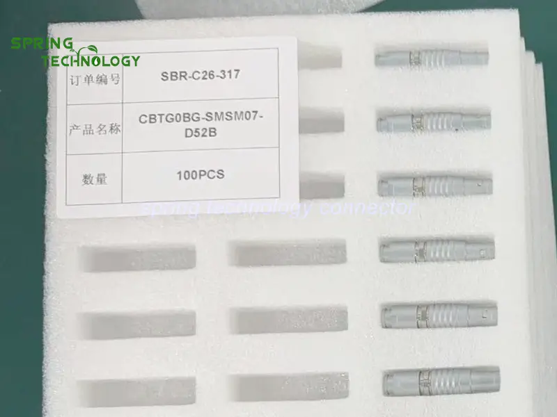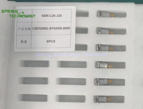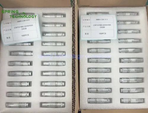


CBTG0BG-SMSM07-D52B Push-Pull Connector for Portable Soil Resistivity Meters 2026: 0B 7-Contact Straight Plug
The CBTG0BG-SMSM07-D52B push-pull connector for portable soil resistivity meters is a 0B-shell, seven-contact solder plug that gives the instrument a detachable auxiliary signal interface between its control unit and a data-logging or auxiliary control module — IP50 when mated, 750 V working voltage and 2.5 A per contact on the 307 insert, PPS insulation, gold-plated brass contacts, and more than 5,000 mating cycles. Soil resistivity surveys are carried out where the grounding grid, the pipeline route or the survey line happens to be, not in a laboratory, so the auxiliary interface has to survive transport, frequent reconnection and gloved-hand operation.
Auxiliary ports are usually the first thing to become a nuisance on a portable instrument: a threaded coupling takes turns to seat, a loose cable interrupts a logging run, and a connector that is larger than the electronics it serves forces a bigger enclosure than the measurement circuit needs. Each reconnection is also a small risk to contact integrity, which matters when the logged values feed a grounding design decision.
Core answer: the CBTG0BG-SMSM07-D52B push-pull connector for portable soil resistivity meters is specified as a 0B straight plug with seven contacts, solder termination, a cable opening of 4.30–5.20 mm for this cable variant and a push-pull self-latching mechanism that seats and releases in a single axial movement. It is not intended to replace the four dedicated measurement electrode terminals of a Wenner array; it is the detachable auxiliary interface inside the instrument electronics, where control signals, status feedback and auxiliary communication circuits can share one compact connector instead of several.
1. Technical Parameters & Engineering Standards
Every value below for the CBTG0BG-SMSM07-D52B push-pull connector is taken from the published 0B platform documentation and from the 307-insert row of the product page P/N table for this seven-contact layout. Values that belong to the specific cable variant are marked as such.
- Latching Mechanism: push-pull self-latching system with a keyed shell (key G, with A…M and R variants) — the coupling seats by an axial push and releases by pulling the outer sleeve, without a threaded collar.
- Recommended Hardware: Spring Technology 0B series circular connectors, with the TGG.0B straight plug as the plug family this article describes.
- Key Metric: more than 5,000 mating cycles, 750 V working voltage, 2.5 A per contact on the 0.5 mm 307 insert, and a maximum contact resistance of 15 mΩ.
1.1 Configuration Summary
| Parameter | Value |
|---|---|
| Model | CBTG0BG-SMSM07-D52B |
| Format | 0B straight cable plug, male solder contacts |
| Contacts | 7 low-voltage contacts (307 insert) |
| Contact size | 0.5 mm |
| Conductor size | AWG 28–30 |
| Working voltage | 750 V |
| Rated current | 2.5 A per contact (307 insert) |
| Contact resistance | ≤15.0 mΩ |
| Termination | Solder |
| Keying | Key G, with A…M and R variants available in the 0B range |
| Cable opening | 4.30–5.20 mm for this cable variant (0B platform opening 1.5–5.5 mm) |
| Insert material | PPS (polyphenylene sulfite) |
| Shell / contacts | Chrome-plated brass shell, gold-plated brass contacts |
| Protection index | IP50 when mated |
Note: the pin assignment, conductor sizes and cable construction should be confirmed against the instrument wiring schedule before the harness is built. The protection rating applies to the mated connector pair, not to the plug alone.
1.2 Shared 0B Platform Specifications
| Parameter | Value |
|---|---|
| Shell size | 0B — eight configurations from 2 to 9 contacts |
| Operating temperature | -45 °C ~ +125 °C |
| Humidity | Up to 95% at 60 °C |
| Vibration resistance | 10–20000 Hz, 15 g |
| Mechanical shock | 100 g · 6 ms |
| Salt spray corrosion test | >48 h |
| Mating cycles | >5,000 |
| Protection index | IP50 when mated |
| Termination | Solder |
| Fastening type | Push-pull |
| Shell material and finish | Brass, chrome plated |
| Contact material and finish | Brass, gold plated |
| Insert material | PPS (polyphenylene sulfite) |
| Cable opening | 1.5–5.5 mm across the 0B platform |
Note: these are platform-level values published for the 0B shell that this CBTG0BG-SMSM07-D52B push-pull connector belongs to, so they describe the family rather than a single supplied assembly. The finished instrument must still be evaluated as a system — enclosure sealing, cable strain relief and the operator’s field handling all sit outside the connector specification.
2. Key Advantages of the CBTG0BG-SMSM07-D52B Push-Pull Connector
An auxiliary port on a field instrument is judged by how little attention it demands. The characteristics below explain why this CBTG0BG-SMSM07-D52B push-pull connector suits this class of field meter and comparable survey electronics:
2.1 Seven Contacts for Multiple Auxiliary Signals
The CBTG0BG-SMSM07-D52B push-pull connector carries seven low-voltage contacts. That count is enough to give the main measurement unit a detachable link to an auxiliary module carrying several distinct functions at once — low-voltage control signals, status feedback and auxiliary communication circuits can share one shell instead of being split across several small connectors.
In a portable soil resistivity meter, the same connector can therefore serve a data-logging module, an auxiliary control panel or a service interface, depending on how the manufacturer assigns the pins. The actual pin assignment must be determined from the instrument’s electrical design; the connector provides the physical paths, not a fixed protocol.
2.2 Push-Pull Locking for Convenient Field Operation
Soil resistivity measurements are taken at whatever locations the survey calls for: construction sites, substations, pipeline routes and geological survey areas. Technicians connect and disconnect auxiliary cables repeatedly while moving the instrument between measurement points, often while wearing gloves.
Portable soil resistivity meters such as the Tinker & Rasor SR-2 are built for exactly this kind of field work: they support several testing configurations, the Wenner four-pin method among them, and many models add a data-logging connection for recording and reviewing measurement results.
The push-pull self-latching mechanism seats with a single axial push and releases with a pull on the outer sleeve. There is no threaded collar to cross-thread or to unwind, and the latch resists accidental release during normal handling and transport. For a portable instrument that sees frequent cable changes, that difference in operating effort accumulates over a survey season.
2.3 Solder Termination for Customized Cable Assemblies
The CBTG0BG-SMSM07-D52B push-pull connector uses solder termination, so individual conductors are soldered directly to the contacts. This gives the harness builder freedom over conductor choice, shielding and the internal wiring of a custom cable assembly — an advantage when the same instrument platform is offered with different auxiliary modules.
Engineers can configure the wiring to match the main control board, the data-logging module and the auxiliary interface at the same time. Soldering procedure, insulation distance and cable strain relief should be controlled as part of the assembly process so that the mechanical load is carried by the cable clamp rather than by the solder joints.
2.4 PPS Insulation for Electrical Separation
The insert of the CBTG0BG-SMSM07-D52B push-pull connector is moulded in PPS (polyphenylene sulfite). In precision measurement equipment, stable contact positioning and predictable insulation between adjacent contacts matter, because the auxiliary circuits often run next to low-level measurement wiring inside the same enclosure.
PPS is the insert material specified across the 0B platform, so a seven-contact plug and the socket it mates with share the same insulation system. That consistency is useful when a manufacturer builds several instrument variants on one connector family.
2.5 Cable Range for Portable Instrument Design
The cable variant specified for this CBTG0BG-SMSM07-D52B push-pull connector accepts an outside diameter of 4.30–5.20 mm, within the 0B platform opening of 1.5–5.5 mm. The range suits the multi-conductor, shielded constructions typical of auxiliary signal cables on portable instruments.
The straight plug body keeps cable routing simple inside a compact enclosure and along an external connection assembly. Where a cable leaves the housing at an angle, the 0B family also includes elbow options, so the harness geometry can be adapted without changing the contact system.
2.6 Mechanical Endurance for Repeated Connection Cycles
Portable soil resistivity meters are used for repeated field campaigns, and their auxiliary connections are disconnected for transport, storage, maintenance and module replacement. The plug is specified for more than 5,000 mating cycles on the 0B platform.
That endurance figure, together with the 100 g · 6 ms shock rating and the 10–20000 Hz vibration rating, describes a connector intended for repeated handling rather than for a one-time installation. For a CBTG0BG-SMSM07-D52B push-pull connector, that endurance is the difference between a connector that is specified for field use and one that simply tolerates it. It does not remove the need for sensible field practice — cap the plug when it is not mated, and avoid pulling on the cable instead of the coupling sleeve.
3. Why Choose the CBTG0BG-SMSM07-D52B Push-Pull Connector for Soil Resistivity Testing Equipment?
Portable soil resistivity meters need a practical electrical interface between the measurement unit, the data-logging module and the auxiliary electronics. The CBTG0BG-SMSM07-D52B push-pull connector addresses that interface with a defined set of characteristics:
- Seven low-voltage contacts for multiple auxiliary signal connections in one shell.
- Push-pull locking for quick connection and disconnection during field work.
- Solder termination for customized cable assemblies and flexible wiring.
- PPS insulation for predictable electrical separation.
- Cable opening of 4.30–5.20 mm for this cable variant.
- More than 5,000 mating cycles for repeated connection requirements.
Two boundaries should be stated plainly. The plug is rated IP50 when mated, so it is not a waterproof solution for exposed outdoor measurement environments and should be used inside or behind a protected enclosure. And it is not a measurement electrode: the four dedicated electrode terminals of a Wenner array carry the excitation and measurement circuits, while this connector serves the auxiliary electronics.
Before implementation, engineers should verify the mating connector, the contact assignment, the cable construction, the current requirements of each auxiliary circuit and the environmental conditions of the finished instrument. The published product information lists a 0B fixed socket and a 0B free socket as suggested matching parts — a ZGG.0B seven-contact panel socket and a DHG.0B seven-contact free socket — and the exact ordering code should be confirmed before assembly.
4. 0B Series Connector Family Overview
The 0B shell is the compact end of the family that this CBTG0BG-SMSM07-D52B push-pull connector belongs to — the 0B series range: eight contact layouts from 2 to 9 positions, solder termination, push-pull self-latching coupling, IP50 when mated and a -45 °C to +125 °C operating range. Instruments that need a smaller interface than the 1B shell but more contacts than the 00B family usually settle on this size.
4.1 Available Configurations
The seven-contact 307 insert used by the CBTG0BG-SMSM07-D52B push-pull connector sits in the middle of the range. Two-contact and three-contact versions handle simple power and status circuits; four, five and six contacts cover the common auxiliary combinations; nine contacts serve denser signal bundles. Plugs, panel sockets and free sockets share the same contact system, so a detachable module can be built with a ZGG.0B fixed socket on the panel side or a DHG.0B free socket on the cable side.
4.2 Customization Services
Beyond the catalogue configurations, Spring Technology builds custom cable assemblies around the 0B platform for the CBTG0BG-SMSM07-D52B push-pull connector: conductor mapping to the instrument wiring schedule, shielding and screening choices, overmoulding or bend relief, labelling and 100% continuity testing before shipment. For soil resistivity meters, the usual request is a plug-to-module harness in which the seven contacts carry a defined mix of control, feedback and communication lines.
5. Frequently Asked Questions (FAQ)
Conclusion & Call to Action
The CBTG0BG-SMSM07-D52B push-pull connector can be considered for the auxiliary signal interface of field survey instruments used in grounding system design, pipeline engineering and geological survey work. Its seven-contact configuration, push-pull locking, solder termination and PPS insulation give the instrument a detachable module link that matches the way field crews actually use the equipment — connect, log, disconnect, move on.
For more information about our 0B series connectors or to discuss your requirements, contact us at [email protected] or [email protected], or visit our website.
Building a portable soil testing instrument? Send us your contact count, cable construction and auxiliary circuit requirements — our engineering team will respond with a tailored connector and harness proposal within 24 hours.
Further Reading
- 0B FIZ Connector 2026: CBTG0BG-SMSM07-D52B and CBZG0BG-SFSM07-0000 Wireless Lens Control Connectors for Russian Client
- Push-Pull Connector for Geophysical Exploration 2026: CBTG3FN-SMSM03-D720 and CBTG4FN-SMSM02-D720 Plugs for Field Survey and Industrial Power
- CBTG0BG Push-Pull Connectors for Industrial Laser Trackers 2026: 5, 6 and 7-Contact 0B Plugs for Precision Metrology Interfaces
- CBTG0BG Push-Pull Connector for Railway Wheel Profile Gauges 2026: 0B 7-Contact Plug
- CBTG0BG Push-Pull Connector for Grain Moisture Analyzers 2026: 0B 5-Contact Probe Plug for Portable Field Meters
- 0B Series Push-Pull Circular Connectors — Configurations, Specifications and Downloads
- TGG.0B Straight Plug — 0B Cable Plug Product Page
- ZGG.0B Fixed Socket — 0B Panel Socket Product Page
- Custom Cable Assembly Services — Connector-to-Module Harnesses