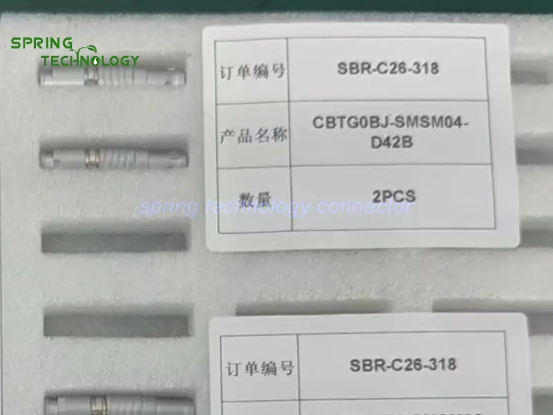


CBTG0BG-SMSM04-D42B Push-Pull Connector for Handheld Digital Force Gauges 2026: 0B 4-Contact USB Straight Plug
The CBTG0BG-SMSM04-D42B push-pull connector is a four-contact 0B straight cable plug built for the detachable data link between a handheld digital force gauge and a computer or logging device — solder termination, push-pull self-latching coupling, USB 2.0 data transmission up to 480 Mbit/s under the published specification, a 3.30–4.20 mm cable opening for this variant, IP50 when mated and more than 5,000 mating cycles. It carries data, not force: the mechanical load of a pull test goes through the gauge’s own load cell and fixture, never through this connector.
Handheld force gauges end up in places where data cables are an afterthought: wire-terminal pull tests on a production line, connector insertion and extraction checks at goods-in, spring-rate measurements in a lab, packaging strength tests at the end of a packing station. The gauge is picked up many times a day, its cable is plugged into a PC when results need to be logged, and unplugged again when the instrument moves to the next station.
Core answer: CBTG0BG-SMSM04-D42B gives that data link a locking, serviceable interface instead of a consumer USB cable plus adapter: four low-voltage contacts on a 0.7 mm contact size rated 7 A per contact and 750 V, a maximum contact resistance of 12.5 mΩ, PPS insulation and a compact straight body that fits a handheld enclosure. The published specification covers USB 2.0 data transmission up to 480 Mbit/s, and the assembly still has to be built as a USB interface — correct pinout, correct cable construction and a proper shield termination.
1. Technical Parameters & Engineering Standards
Every value below for the CBTG0BG-SMSM04-D42B push-pull connector comes from the published 0B platform documentation and from the 304 four-contact insert row of the product page P/N table. Items that depend on the cable variant or the equipment design are marked as such.
- Latching Mechanism: push-pull self-latching system — the plug seats with an axial push and releases by pulling the outer sleeve, with a keyed shell (key G, with A…M and R variants) so a neighbouring interface cannot be cross-mated.
- Recommended Hardware: the TGG.0B straight plug on the data cable and a 0B panel socket on the instrument or on the interface box, both from the Spring Technology 0B range.
- Key Metric: 4 contacts on a 0.7 mm insert, 750 V working voltage, 7 A per contact, ≤12.5 mΩ contact resistance, USB 2.0 data up to 480 Mbit/s, IP50 when mated and more than 5,000 mating cycles.
1.1 Configuration Summary
| Parameter | Value / Status |
|---|---|
| Model | CBTG0BG-SMSM04-D42B |
| Body | 0B straight cable plug, male solder contacts, compact shell |
| Contacts | 4 (304 insert) |
| Contact size | 0.7 mm |
| Conductor size | AWG 22–26 |
| Working voltage | 750 V |
| Rated current | 7 A per contact (connector rating, not the USB bus current) |
| Contact resistance | ≤12.5 mΩ |
| Data interface | USB 2.0, up to 480 Mbit/s under the published specification — with the correct pinout, cable construction and shield termination |
| Termination | Solder |
| Cable opening | 3.30–4.20 mm for this cable variant (0B platform opening 1.5–5.5 mm) |
| Keying | Key G, with A…M and R variants available in the 0B range |
| Insert material | PPS (polyphenylene sulfite) |
| Protection index | IP50 when mated |
Note: the USB pin assignment, cable impedance and shield termination belong on the assembly drawing. The protection rating applies to the mated pair, not to the plug alone.
1.2 Shared 0B Platform Specifications
| Parameter | Value |
|---|---|
| Shell size | 0B — layouts from 2 to 9 contacts |
| Operating temperature | -45 °C ~ +125 °C |
| Humidity | Up to 95% at 60 °C |
| Vibration resistance | 10–20,000 Hz, 15 g |
| Mechanical shock | 100 g · 6 ms |
| Salt spray corrosion test | >48 h |
| Mating cycles | >5,000 |
| Protection index | IP50 when mated |
| Termination | Solder |
| Fastening type | Push-pull |
| Shell material and finish | Brass, chrome plated |
| Contact material and finish | Brass, gold plated |
| Insert material | PPS (polyphenylene sulfite) |
| Cable opening | 1.5–5.5 mm across the 0B platform |
Note: these are platform-level values published for the 0B shell, so they describe the connector family rather than a single supplied assembly.
2. Key Advantages of the CBTG0BG-SMSM04-D42B Push-Pull Connector
A data connector on a force gauge is not a feature anyone buys the instrument for — it is the part that has to stop being a problem. The characteristics below explain why this CBTG0BG-SMSM04-D42B push-pull connector suits handheld measurement equipment:
2.1 Four Contacts for USB 2.0 Data Transmission
The plug carries four low-voltage contacts on a 0.7 mm contact size and is published for USB 2.0 data transmission up to 480 Mbit/s. That maps naturally onto the four conductors a USB 2.0 link needs — VBUS, D−, D+ and ground — when the pin assignment is defined correctly on the assembly drawing.
Handheld instruments such as the Wagner FORCE TEN FDX pair peak-force measurement and a digital display with a USB data output, and the cable that carries that output to a computer is exactly the interface this connector serves. For a digital force gauge, that is the path by which peak values, test curves and pass/fail results reach a PC for logging, statistics and inspection reports, so the connector is a data interface rather than a power interface.
2.2 Push-Pull Locking for Secure Cable Connections
Force gauges move between production lines, inspection stations and the laboratory, and their data cable is connected and disconnected all day. The plug mates with a push-pull self-latching action — an axial push to seat, a pull on the outer sleeve to release — so there is no thumb screw to lose and no friction fit to work loose.
On the CBTG0BG-SMSM04-D42B push-pull connector, the latch resists the accidental tug that comes from a cable draped over a bench edge or caught when the gauge is lifted, which is how a consumer USB socket on a handheld instrument usually ends up intermittent.
2.3 Compact Straight Plug for Handheld Equipment
The CBTG0BG-SMSM04-D42B push-pull connector is a straight cable-mounted plug in the compact 0B shell. On a handheld instrument the shell diameter sets how much of the enclosure has to be dedicated to the connector, and a straight body keeps the cable leaving the gauge in a predictable direction instead of turning through a bend radius the enclosure was not designed for.
That matters when the gauge is used with its display facing the operator and the cable has to fall away from the test fixture rather than across it.
2.4 Solder Termination and a Defined Cable Range
Termination in the CBTG0BG-SMSM04-D42B push-pull connector is by solder, so the assembly can follow the instrument’s own harness rather than a pre-crimped pigtail. This cable variant accepts an outside diameter of 3.30–4.20 mm, inside the 0B platform opening of 1.5–5.5 mm, which covers the shielded multi-conductor constructions a USB 2.0 link needs.
Conductor selection, soldering procedure, cable shielding and strain relief should all be controlled as part of the assembly process; on a data link, a poorly terminated shield is often the reason a link that works on the bench fails next to a motor drive.
2.5 PPS Insulation for Contact Separation
The insert in the CBTG0BG-SMSM04-D42B push-pull connector is moulded in PPS (polyphenylene sulfite), the material specified across the 0B platform. It holds the four contacts at a fixed spacing and provides predictable insulation between them, which is what a differential pair needs if the impedance is to stay controllable along the whole cable.
Stable contact positioning also affects repeatability of the data link: a contact that shifts under cable load changes the geometry of the pair at the transition point.
2.6 Shielding Performance in Manufacturing Environments
The published specification for the plug of the CBTG0BG-SMSM04-D42B push-pull connector lists a minimum shielding performance of 75 dB at 10 MHz and 40 dB at 1 GHz. Force gauges are used next to motors, servo drives and automated machinery, so a shielded assembly with a properly bonded screen is what keeps a USB link from being reset by switching noise.
The figure is a connector-level property. Real EMC performance depends on the complete assembly: cable shield, termination at both ends, grounding and the instrument’s enclosure design.
2.7 Mechanical Endurance for Repeated Testing Operations
The CBTG0BG-SMSM04-D42B push-pull connector is specified for more than 5,000 mating cycles on the 0B platform. Force gauges run repeated inspection tasks — wire pull tests, insertion force checks, packaging strength tests — and the data cable is disconnected for transport, re-routing and maintenance throughout that service life.
That is the same endurance the 0B family provides on the instrument side, so a gauge that is re-cabled several times a year never becomes the weak point of its own data path.
3. Why Choose the CBTG0BG-SMSM04-D42B for Digital Force Gauges?
Handheld digital force gauges need a dependable way to hand measurement results to a computer, and the connector is the part that decides whether that handover is repeatable. The CBTG0BG-SMSM04-D42B push-pull connector offers the characteristics below:
- Four low-voltage contacts for a USB 2.0 interface design.
- Published USB 2.0 data transmission up to 480 Mbit/s.
- Push-pull locking for repeated connection and disconnection.
- Compact straight plug for portable enclosures.
- Solder termination and a 3.30–4.20 mm cable range.
- PPS insulation for predictable contact separation.
- Shielding performance specified for the plug when the harness is properly built.
- More than 5,000 mating cycles.
Three boundaries are worth stating plainly. First, the connector does not by itself set the data rate: 480 Mbit/s is a property of the complete USB 2.0 link — pinout, cable impedance, shield termination, host and device — and a four-contact connector with a poorly built harness will fall back or fail. Second, the protection rating is IP50 when mated, which suits indoor or protected environments and does not make the interface waterproof. Third, this is a data interface, not a load-bearing element: the force of a pull test must never pass through the connector or its cable.
Before integration, engineers should verify the mating connector, the USB pin assignment, the cable impedance, the shielding and grounding scheme, and the signal integrity of the finished assembly.
4. 0B Series Connector Family Overview
The 0B shell is the compact member of the 0B series: layouts from 2 to 9 contacts, solder termination, push-pull self-latching coupling, IP50 when mated and a -45 °C to +125 °C operating range. Handheld instruments that need a smaller interface than the 1B shell but more contacts than the 00B family usually settle on this size.
4.1 Available Configurations
Four contacts is the smallest layout that still covers a USB 2.0 link with a spare or a dedicated ground, which is why the 304 insert is common on data interfaces. Two and three contacts serve power and status circuits; five to nine contacts serve denser signal bundles. Plugs, panel sockets and free sockets share the same contact system.
For the CBTG0BG-SMSM04-D42B push-pull connector, the plug travels with the data cable while a 0B panel socket stays on the instrument or on an interface box — the arrangement that keeps the gauge sealed and the cable replaceable.
4.2 Customization Services
Beyond the catalogue configurations, Spring Technology builds custom cable assemblies around the 0B platform for the CBTG0BG-SMSM04-D42B push-pull connector: conductor mapping to the instrument’s USB design, shielded pair construction, overmoulding or bend relief, labelling and 100% continuity testing before shipment.
5. Frequently Asked Questions (FAQ)
Conclusion & Call to Action
The CBTG0BG-SMSM04-D42B push-pull connector gives a handheld digital force gauge a data interface that locks, releases without tools and survives more than 5,000 mating cycles: four contacts on a 0.7 mm insert, a published USB 2.0 path up to 480 Mbit/s, a compact straight body for handheld enclosures and a 3.30–4.20 mm cable range for a shielded data harness.
For more information about our 0B series connectors or to discuss your requirements, contact us at [email protected] or [email protected], or visit our website.
Building a handheld measurement instrument with a detachable data link? Send us your USB pinout, cable requirements and enclosure constraints — our engineering team will respond with a tailored connector and cable proposal within 24 hours.
Further Reading
- 0B Precision Sensor Connector 2026: CBTG0BG-SMSM05-D52B Plug and CBZG0BG-SFSM05-0000 Socket for Load Cells and Accelerometers
- CBTN1BG Push-Pull Connectors for Coating Thickness Gauges 2026: TN Body Style 1B Series 2-Pin Connectors
- Connectors for USB Industrial Data Loggers 2026: CBTN1BA-SMSM04-D52B Four-Contact Lanyard-Release Plug
- CBTG0BC Push-Pull Connector for CNC Commissioning Terminals 2026: 0B 4-Contact USB 2.0 Plug
- CBTG1BG Push-Pull Connector for Video Borescope Processors 2026: 1B 8-Contact High-Speed Plug
- 0B Series Push-Pull Circular Connectors — Configurations, Specifications and Downloads
- TGG.0B Straight Plug — 0B Cable Plug Product Page
- Custom Cable Assembly Services — USB Data Cable Harnesses