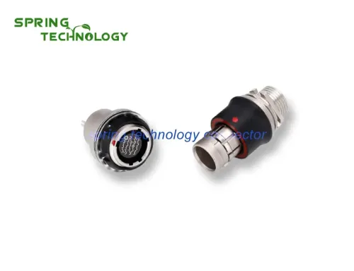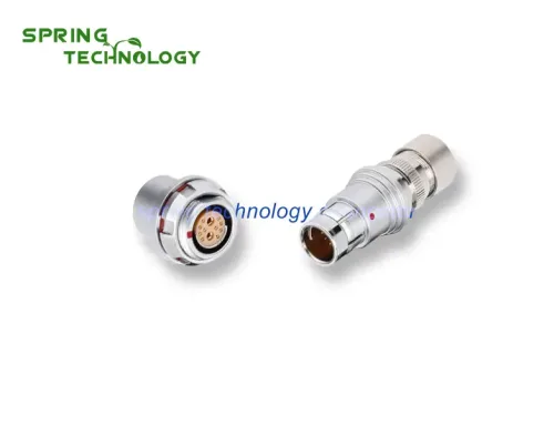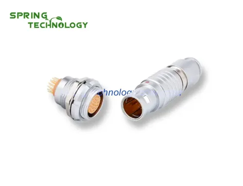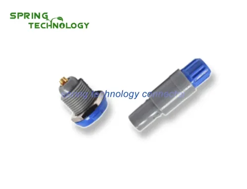


Choosing the right electronic connector is critical for ensuring reliable electrical continuity in your application. The main consideration is maintaining contact pair continuity during connector vibration, shock, and impact at specific frequencies and accelerations. Under dynamic stress conditions, contact pairs may experience instantaneous open circuits—typically specified as 1 μs, 10 μs, 100 μs, 1 ms, or 10 ms. Industry standards now define connection failure when voltage drop across closed contact pairs exceeds 50% of the power electromotive force, considering both duration and voltage drop criteria.
According to 2025 industry data, the global electronic connector market is valued at $78.5 billion, with improper connector selection accounting for nearly 30% of field failures in electronic systems. This comprehensive guide covers all critical factors for connector selection to help engineers make informed decisions for their specific applications.

Connection Mode: Selecting the Right Mating System
A connector typically consists of a plug (free-end connector) and socket (fixed connector). Circuits connect and disconnect through plug-socket engagement, resulting in various connection methods. For circular connectors, three primary connection modes exist:
Threaded Connection
Threaded connectors are the most common type, featuring simple processing technology, low manufacturing costs, and wide application range. However, the slow connection speed makes them unsuitable for applications requiring frequent plugging and rapid connection.
Bayonet Connection
Bayonet connectors feature three bayonet slots enabling faster connection speeds. The longer slot design allows quick engagement but increases manufacturing complexity and cost compared to threaded alternatives.
Push-Pull (Pin) Connection
Push-pull connectors offer the fastest connection mode—requiring only linear motion for connection, disconnection, and locking. This direct push-pull mechanism eliminates rotational requirements but is typically suitable for connectors with lower total separation forces, commonly found in miniature connector designs.
Installation Method and Appearance Considerations
Mounting Options
Connectors install via front mounting or rear mounting configurations. Installation and fixing methods include:
- Rivets: Permanent installation for high-vibration environments
- Screws: Removable mounting for maintenance access
- Snap Rings: Quick installation with secure retention
- Quick Locking: Tool-free installation using connector’s integrated locking mechanism
Form Factor Selection
Connector shape continues evolving to meet diverse application needs. Selection criteria include:
- Straight vs. right-angle cable exit
- Wire or cable outer diameter compatibility
- Housing fixing requirements
- Volume and weight constraints
- Metal hose connection requirements
- Panel-mounted connector aesthetics (shape, color, finish)
Environmental Parameters: Critical Selection Factors
Environmental parameters significantly impact electronic connector performance and reliability. Key factors include ambient temperature, humidity, temperature changes, atmospheric pressure, and corrosive environments. Connector use, storage, and transportation environments must guide corresponding selection decisions.
Ambient Temperature
Connector metal and insulating materials determine operating temperature ranges. High temperatures can damage insulating materials, reducing insulation resistance and dielectric withstand performance. For metals, elevated temperatures cause contact pairs to lose elasticity, accelerate oxidation, and degrade contact plating.
Standard temperature range: -55°C to +100°C (higher for specialized applications)
Humidity and Moisture Resistance
Relative humidity exceeding 80% is the primary cause of electrical breakdown. Humid environments cause water vapor absorption and diffusion on insulator surfaces, potentially reducing insulation resistance below 1 MΩ. Prolonged high-humidity exposure causes:
- Physical deformation and material decomposition
- Respiratory effects and electrolysis
- Corrosion and cracking
- Insulation resistance degradation
For external equipment connectors, always consider humidity, water penetration, and pollution environmental conditions. Sealed connectors with appropriate IP ratings (per GB4208/IEC60529) are essential for waterproof and dustproof applications.
Rapid Temperature Changes
Rapid temperature change testing simulates actual connector equipment use in cold-to-warm transitions or spacecraft/detector ambient temperature fluctuations. Sudden temperature changes may cause:
- Insulation material cracking
- Layer delamination
- Seal integrity compromise
- Contact resistance variation
Atmospheric Pressure
At high altitudes with thin air, plastics release gases that pollute contact pairs, increase corona tendency, and reduce dielectric withstand performance—potentially causing short circuit faults. At certain high-altitude values, plastic materials may experience outgassing and structural degradation.
Electrical Performance Requirements
Contact Resistance
Contact resistance directly affects signal integrity and power transmission efficiency. Premium connectors maintain contact resistance below 50 mΩ initial, with less than 10 mΩ variation after environmental testing.
Current Rating
Current capacity depends on contact material, plating, and contact area. Electronic connectors range from signal-level (under 1A) to power applications (50A+ per contact).
Voltage Rating
Voltage withstand capability determined by contact spacing, insulation material, and environmental conditions. Standard ratings range from 50V (signal) to 5kV (high-voltage power).
Shielding Effectiveness
EMI/RFI shielding protects sensitive signals from electromagnetic interference. Shielded connectors provide 60-80 dB attenuation across frequency spectrum (DC to 10 GHz).
Mechanical Performance Criteria
Mating Cycle Life
Connector durability measured by mating cycles without performance degradation. Industry standards:
- Commercial grade: 500-1,000 cycles
- Industrial grade: 1,000-5,000 cycles
- Military/Aerospace grade: 5,000-10,000+ cycles
Vibration and Shock Resistance
Connectors must maintain electrical continuity under mechanical stress. Testing per MIL-STD-202, IEC 60068-2-6 specifies performance at frequencies from 10 Hz to 3,000 Hz with accelerations up to 60G.
Cable Retention
Cable pull-out strength ensures reliable wire-to-connector attachment. Minimum retention forces range from 10 lbs (signal cables) to 100+ lbs (power cables).
Material Selection and Plating
Contact Materials
- Copper Alloy: Excellent conductivity, moderate cost (C36000, C51000)
- Beryllium Copper: High strength, good conductivity (C17200)
- Phosphor Bronze: Good spring properties, corrosion resistance
Contact Plating
- Gold Plating: Lowest contact resistance, best corrosion resistance (0.05-2.5 μm thickness)
- Nickel Plating: Hard barrier layer, wear resistance
- Tin Plating: Cost-effective, good solderability
- Silver Plating: Highest conductivity, tarnish susceptibility
Housing Materials
- Thermoplastic: PBT, PA66, PC (cost-effective, good dielectric)
- Thermoset: DAP, BMC (high temperature, dimensional stability)
- Metal: Aluminum alloy, brass (EMI shielding, mechanical strength)
2026 Connector Selection Trends
The electronic connector industry continues evolving with several key developments:
- Miniaturization: Smaller form factors maintaining full performance (30% size reduction since 2020)
- High-Speed Data: Support for USB 3.2, Ethernet 10GbE, PCIe in ruggedized packages
- Hybrid Configurations: Combined power, signal, fiber optic, and fluid contacts
- Smart Connectors: Integrated sensors for connection monitoring and predictive maintenance
- Sustainable Materials: Recyclable housings, RoHS-compliant plating, reduced precious metal usage
- Modular Designs: Field-configurable contact arrangements reducing inventory costs
Industry-Specific Selection Guidelines
Medical Devices
Medical electronic connectors require biocompatibility, sterilization resistance, and reliable performance. Key considerations include IP67/IP68 sealing, gold plating for low contact resistance, and compliance with IEC 60601-1 medical electrical equipment standards.
Industrial Automation
Factory environments demand rugged connectors with high vibration resistance, wide temperature operation, and IP65+ protection. Push-pull connectors excel in applications requiring frequent connection changes.
Telecommunications
5G infrastructure requires high-frequency connectors with excellent shielding, low insertion loss, and outdoor environmental protection (IP67/IP68). Fiber optic hybrid connectors gaining adoption for combined power/data transmission.
Defense and Aerospace
Military specifications (MIL-DTL-38999) mandate extreme reliability under harsh conditions. Connectors must withstand wide temperature ranges (-55°C to +200°C), salt spray, altitude, and electromagnetic pulse (EMP) events.
Automotive
Automotive connectors face vibration, temperature cycling, and chemical exposure. USCAR and LV214 standards define performance requirements. Electrification trends drive high-voltage connector development (400V-800V systems).
Conclusion
Selecting the right electronic connector requires careful evaluation of electrical, mechanical, environmental, and application-specific requirements. The connection mode, installation method, environmental parameters, and material selection all contribute to overall system reliability and performance.
When choosing an electronic connector, consider factors including operating environment, required mating cycles, electrical specifications, mechanical constraints, regulatory compliance, and total cost of ownership. Proper connector specification ensures reliable electrical connections throughout the product lifecycle while minimizing field failures and maintenance costs.
As electronic systems advance toward higher speeds, smaller form factors, and harsher operating conditions, connector selection will continue playing a critical role in enabling next-generation electrical interconnection solutions. Understanding fundamental selection principles enables engineers to make informed decisions for their specific application requirements.
Frequently Asked Questions (FAQ)
Q1: What is the most important factor when choosing an electronic connector?
A: The most critical factor is matching the connector’s environmental and electrical ratings to your application requirements. Consider operating temperature, humidity, vibration levels, current/voltage needs, and mating cycle expectations before selecting a connector type.
Q2: How do I determine the correct contact plating for my application?
A: Gold plating offers best performance for low-voltage signal applications requiring high reliability (medical, aerospace, test equipment). Tin plating is cost-effective for consumer electronics and automotive applications. Nickel plating serves as excellent underplating or for harsh environment housings.
Q3: What IP rating do I need for outdoor applications?
A: For outdoor applications, minimum IP65 rating protects against water jets. IP67 provides temporary immersion protection (30 minutes at 1 meter). IP68 offers continuous submersion resistance. IP69K handles high-pressure, high-temperature washdown conditions.
Q4: How many mating cycles should I expect from a quality connector?
A: Commercial-grade connectors typically provide 500-1,000 mating cycles. Industrial-grade connectors offer 1,000-5,000 cycles. Military/aerospace connectors with gold plating achieve 5,000-10,000+ cycles with proper maintenance.
Q5: What is the difference between threaded and push-pull connectors?
A: Threaded connectors offer secure, vibration-resistant connections but require rotational motion and longer mating time (3-5 seconds). Push-pull connectors enable rapid connection (under 1 second) with simple axial motion, ideal for frequent connection changes and confined spaces.
Extended Reading
- What Is Push-Pull Circular Connector? – Understanding self-latching connector technology and applications
- Connector Plating Guide: Gold vs Nickel vs Tin Plating – Comprehensive plating material selection criteria
- How Does Push-Pull Circular Connector Work? – Detailed explanation of connector mating mechanisms