

Description: This comprehensive guide covers the theoretical standards of aviation plugs (aeronautics connectors), including rated voltage, rated current, contact resistance, and shielding requirements. Learn about key electrical parameters for selecting aerospace connectors in 2026.

1. Introduction: Understanding Aviation Plug Standards
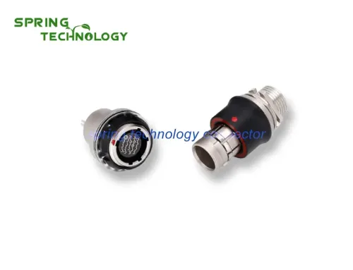
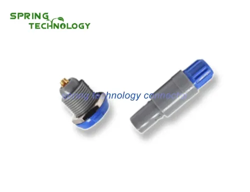
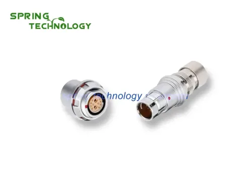
Aviation plugs (also known as aeronautics connectors or aerospace connectors) are electromechanical components that connect electrical circuits in aircraft and aerospace systems. The electrical parameters of the aviation plug itself are the primary consideration when selecting the right connector for your application.
This guide covers the fundamental theoretical standards of aviation plugs, including rated voltage, rated current, contact resistance, and shielding requirements. Understanding these parameters is essential for ensuring reliable performance in demanding aerospace environments.
With the global aerospace connector market projected to reach USD 5.8 billion by 2026 (CAGR 4.2%), selecting connectors that meet rigorous industry standards is critical for flight safety and system reliability.
2. Rated Voltage: Working Voltage Standards
2.1 Definition of Rated Voltage
The rated voltage (also called working voltage) is the maximum continuous voltage that an aviation plug can safely handle during normal operation. This parameter fundamentally depends on:
- The insulating material used in the aviation plug
- The distance (creepage and clearance) between contact pairs
- Environmental conditions (altitude, temperature, humidity)
2.2 Voltage Rating Considerations
Some components or equipment may not perform their functions properly when operating below their rated voltage. The rated voltage of the aviation plug should be recognized as the highest working voltage recommended by the manufacturer.
According to industry standards, aviation plugs can operate normally at voltages lower than the rated voltage. However, operating above the rated voltage can cause:
- Insulation breakdown
- Electrical arcing
- Premature connector failure
- Safety hazards in aerospace applications
2.3 High-Voltage Applications in Aerospace
Modern aircraft systems increasingly operate at higher voltages (270V DC and 115V AC) to reduce weight and improve efficiency. Aviation connectors must be rated appropriately for these applications while maintaining safety margins.
3. Rated Current: Current-Carrying Capacity
3.1 Definition of Rated Current
The rated current (also called working current) is the maximum continuous current that an aviation plug can carry without exceeding temperature limits. Similar to rated voltage, aviation plugs generally operate normally when the working current is below the rated current.
3.2 Thermal Design Considerations
In the design process of aviation plugs, the rated current requirement is satisfied through thermal design. When current flows through the contact pair, the contacts heat up due to:
- Conductor resistance
- Contact resistance
- Environmental heat load
When the heat exceeds a certain threshold, it can damage the insulation of the aviation plug and degrade the plating on the contact surface, causing reliability issues.
3.3 Current Derating for Multi-Contact Connectors
An important consideration when selecting aviation plugs: For multi-contact connectors, the rated current must be derated. This is because:
- Multiple current-carrying contacts generate cumulative heat
- Limited heat dissipation in dense connector configurations
- Adjacent contacts affect each other’s temperature rise
Manufacturers provide derating curves that show the allowable current per contact based on the number of loaded contacts.
4. Contact Resistance: Electrical Connection Quality
4.1 Understanding Contact Resistance
Contact resistance refers to the resistance at the interface between two mating contacts in the connector. This parameter is critical for signal integrity and power transmission efficiency.
Two important points should be noted when evaluating contact resistance:
- The contact resistance specification of an aviation plug actually includes both the contact interface resistance and the conductor (wire) resistance. Since conductor resistance is typically small, contact resistance is often used interchangeably in technical specifications.
- For circuits carrying small signals, pay attention to the test conditions under which the contact resistance specification is measured.
4.2 Film Resistance and Surface Contamination
Since contact surfaces may be covered with oxide layers, oil stains, or other contaminants, a film resistance exists at the mating interface. This film resistance can:
- Increase overall contact resistance
- Cause signal degradation in low-level circuits
- Lead to intermittent connections
High-quality aviation plugs use gold or silver plating to minimize oxidation and maintain low contact resistance over thousands of mating cycles.
4.3 Contact Resistance Requirements by Application
| Application Type | Typical Contact Resistance | Key Consideration |
|---|---|---|
| Power transmission | < 5 mΩ | Minimize voltage drop and heat |
| Signal transmission | < 10 mΩ | Maintain signal integrity |
| Low-level signals | < 50 mΩ (stable) | Prevent noise and intermittent connections |
5. Shielding: Electromagnetic Compatibility (EMC)
5.1 EMI/RFI Shielding Requirements
In modern electrical and electronic equipment, the density of components and increasing functionality impose strict limitations on electromagnetic interference (EMI). Aviation plugs are typically enclosed in metal shells to:
- Block internal electromagnetic energy radiation
- Protect against external electromagnetic fields
- Ensure electromagnetic compatibility (EMC)
5.2 Shielding Effectiveness by Frequency
Shielding requirements vary by frequency range:
- Low frequencies: Only magnetic materials can effectively shield magnetic fields
- High frequencies: Conductive materials provide effective electric field shielding
- Broadband applications: Multi-layer shielding may be required
5.3 Shell Electrical Continuity
Industry standards specify requirements for the electrical continuity of metal shells, including shell contact resistance. Proper shell grounding ensures:
- Effective EMI/RFI shielding
- Lightning strike protection
- Electrostatic discharge (ESD) dissipation
6. Additional Critical Parameters for Aviation Plugs
6.1 Insulation Resistance
Insulation resistance measures the resistance between contacts and between contacts and the shell. Typical requirements:
- ≥ 1000 MΩ @ 500V DC (standard)
- ≥ 5000 MΩ for high-reliability applications
- Tested under specified temperature and humidity conditions
6.2 Dielectric Strength
Dielectric strength (withstand voltage) tests the insulation’s ability to resist electrical breakdown. Aviation plugs must withstand test voltages significantly higher than rated voltage without breakdown or flashover.
6.3 Environmental Ratings
Aviation connectors must meet stringent environmental standards:
- Temperature range: -55°C to +125°C (typical)
- Humidity: Up to 95% RH
- Vibration and shock: Per MIL-DTL-38999 or equivalent
- Salt spray: 48-96 hours for corrosion resistance
7. 2026 Aerospace Connector Industry Trends
7.1 Market Growth and Drivers
The global aerospace connector market continues to grow, driven by:
- Increased aircraft production (commercial and military)
- More electric aircraft (MEA) architectures
- Advanced avionics and communication systems
- Space exploration and satellite deployment
7.2 Miniaturization and High-Density Designs
Modern aerospace systems demand smaller, lighter connectors with higher contact density. This trend requires advances in:
- Materials science
- Precision manufacturing
- Signal integrity engineering
7.3 Enhanced Reliability Standards
As aerospace systems become more complex, connector reliability requirements continue to increase. Industry standards such as AS9100 and MIL-DTL specifications ensure consistent quality and performance.
Conclusion
Understanding the theoretical standards of aviation plugs—including rated voltage, rated current, contact resistance, and shielding—is essential for selecting the right connectors for aerospace applications. These electrical parameters directly impact system reliability, safety, and performance.
As the aerospace industry advances toward more electric aircraft and advanced avionics systems in 2026, choosing aviation connectors that meet or exceed industry standards becomes increasingly critical. Always consult manufacturer specifications and applicable standards when selecting connectors for your aerospace applications.
FAQ
Q1: What is the difference between rated voltage and working voltage?
A: Rated voltage and working voltage are often used interchangeably. The rated voltage is the maximum continuous voltage recommended by the manufacturer. Aviation plugs can safely operate at any voltage below the rated value.
Q2: Why must current be derated for multi-contact connectors?
A: Multiple current-carrying contacts generate cumulative heat, and limited heat dissipation in dense configurations causes temperature rise. Derating ensures no contact exceeds its temperature limit.
Q3: What contact resistance is acceptable for aviation plugs?
A: Typical contact resistance requirements are < 5 mΩ for power applications and < 10 mΩ for signal applications. Low-level signal circuits may require stable resistance < 50 mΩ.
Q4: How does shielding protect aviation connectors?
A: Metal shells block electromagnetic interference (EMI) and radio frequency interference (RFI), protecting signal integrity and preventing the connector from radiating interference to other systems.
Extended Reading
Explore more about aerospace connector technology:
Xi’an spring technology Co., Ltd. is a professional push pull connector manufacturer integrating connector research and development, production and sales.
Contact me for more info and best price: [email protected], [email protected]
Visit our website: https://www.spring-connectors.com/