

CBTF1SA-TMS405-D320 and CBZR1SA-TFS405-0000 High-Voltage Connectors for Dielectric Withstand Test Stations 2026
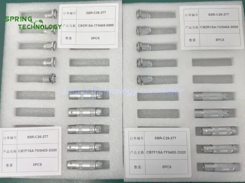
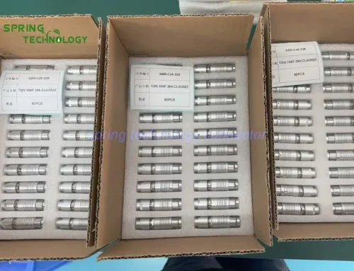
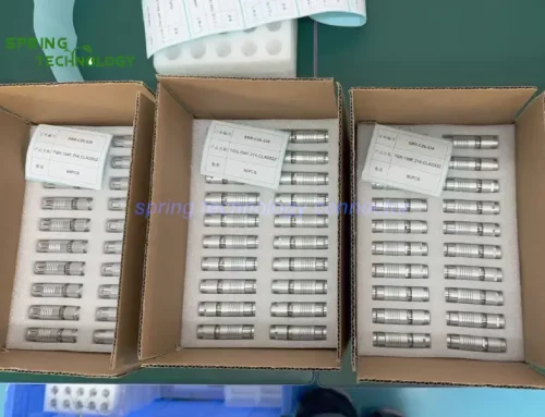
Spring Technology supplies the CBTF1SA-TMS405-D320 high-voltage plug and the CBZR1SA-TFS405-0000 panel receptacle for evaluation in high-voltage cable assembly dielectric withstand test stations — a single high-voltage contact, a rated current of 8 A, a DC test voltage of 10.5 kV, IP50 protection, a published mating endurance of 5,000 cycles, brass contacts with gold-plated mating surfaces, an M12 panel drill hole and push-pull self-locking. Every specification in this guide is backed by the high-voltage test equipment interconnect engineering of Spring Technology.
Pain point: Bringing a controlled dielectric test voltage out of the instrument and into a frequently changed test fixture — where the interface must be defined, detachable, accessible on the panel, and never mistaken for a connector rating that alone makes a high-voltage connection safe to touch?
Core answer: Spring Technology offers a compatible high-voltage plug and panel receptacle that can be evaluated as part of the detachable electrical interface in this type of equipment, supporting a defined test interface, convenient panel integration and efficient maintenance when the selected mating components are compatible. High-voltage cable assembly dielectric withstand test stations evaluate electrical insulation in cables, wiring harnesses and electrical assemblies before they are released for use, applying a controlled test voltage to verify whether insulation can withstand the specified electrical stress without breakdown. A typical station includes a high-voltage source, control electronics, a test fixture, safety interlocks and a connection interface between the instrument and the test object — and the CBTF1SA-TMS405-D320 plug and CBZR1SA-TFS405-0000 receptacle should only be used together after their mating compatibility and complete specifications have been confirmed.
1. Technical Parameters & Engineering Standards
Both parts in this high-voltage connectors for dielectric withstand test stations pairing are built on the 1S unipole platform, a single-contact circular connector family for high-voltage and coaxial test circuits.
- Latching Mechanism: Push-pull self-locking (convenient mating and unmating without a threaded coupling operation)
- Recommended Hardware: Spring Technology Circular Connector and custom cable assembly service
- Key Metric: 1 high-voltage contact; 8 A; 10.5 kV DC test voltage; IP50; 5,000 mating cycles
| Parameter | Value |
|---|---|
| Plug (this order) | CBTF1SA-TMS405-D320 — 1S straight unipole plug, solder termination |
| Receptacle (this order) | CBZR1SA-TFS405-0000 — 1S fixed unipole socket, front-mounted panel, M12 panel drill hole |
| Contacts | 1 high-voltage contact (unipole) |
| Rated current | 8 A |
| DC test voltage | 10.5 kV |
| Protection | IP50 (mated) |
| Mating cycles | 5,000 cycles |
| Contact material / finish | Brass with gold-plated mating surface |
| Termination | Solder |
| Operating temperature | -45 °C ~ +125 °C (1S platform) |
| Vibration resistance | 10~20000 Hz, 15 g |
| Shock resistance | 100 g · 6 ms |
Note: the connector’s own rating must not be treated as the complete system’s allowable operating voltage. The test station’s maximum voltage, transient conditions, insulation coordination, creepage and clearance distances, connector mounting and cable termination must all be reviewed as part of the complete design.
2. High-Voltage Connector Design Highlights
Dielectric test stations are serviced and reconfigured. The design advantages below explain why these high-voltage connectors for dielectric withstand test stations suit instrument-to-fixture interfaces:
2.1 A Defined Interface for High-Voltage Test Circuits
- Dielectric withstand testing requires a carefully designed electrical path between the test instrument and the cable assembly under evaluation. A dedicated high-voltage connector provides a defined physical interface between compatible components, helping organise the test station’s wiring and making the connection point easier to identify during equipment assembly and servicing. The selected connector must be rated for the actual test voltage, current, insulation requirements and intended test procedure.
2.2 Detachable Connections for Test-Fixture Maintenance
- Cable testing equipment may need different fixtures or adapters to accommodate various cable assemblies and test configurations. A detachable connector interface lets technicians disconnect a compatible test lead or serviceable assembly without rewiring the entire instrument, simplifying maintenance and reducing the work required when replacing damaged cables or servicing a test fixture. Any disconnection must take place only after the equipment has been placed in a safe state and the high-voltage circuit has been discharged and verified as de-energized.
2.3 Push-Pull Locking for Convenient Connection
- The 1S series includes connectors with a push-pull self-locking mechanism. For a compatible plug-and-receptacle combination, this mechanism supports convenient mating and unmating without a threaded coupling operation — helpful when technicians handle detachable connections during fixture setup and routine maintenance. The exact locking arrangement and mating compatibility must be verified for the complete part numbers: a locking mechanism alone does not provide electrical interlocking or make a high-voltage connection safe to disconnect while energized.
2.4 Panel-Mounted Integration for Equipment Layouts
- The CBZR1SA-TFS405-0000 is a fixed, front-mounted receptacle designed for panel installation with an M12 panel drill hole, giving equipment designers a defined mounting arrangement for integrating the connector into a test instrument enclosure. A panel-mounted interface helps separate the external test connection from the internal wiring and electronics, and makes the connection point more accessible for operators and service personnel. The panel, insulation barriers, spacing and enclosure must be designed to meet the applicable high-voltage safety requirements.
2.5 Specifications for Engineering Evaluation
- The published product information lists one high-voltage contact, a rated current of 8 A, a DC test voltage of 10.5 kV, an IP50 rating and a published mating endurance of 5,000 cycles. These specifications help engineers assess whether the receptacle is a candidate for a particular test interface, but they do not by themselves establish suitability for every high-voltage test application.
2.6 Support for Organized Testing and Servicing
- A clearly defined connector interface helps standardise the connection between the test instrument and compatible test fixtures. When the connector, cable assembly and fixture are correctly specified and documented, technicians can follow consistent setup and maintenance procedures, making component replacement and troubleshooting more straightforward. For production testing, the complete assembly should be inspected and electrically validated according to the equipment manufacturer’s test procedure and relevant safety standards.
3. Why Consider Connectors for High-Voltage Cable Testing Equipment?
High-voltage cable test stations need connection components selected for the intended electrical stress, mechanical installation and maintenance workflow. These high-voltage connectors for dielectric withstand test stations are worth evaluating where a detachable, panel-mounted interface is required:
- A defined connection point for the high-voltage test circuit
- Convenient servicing of compatible test leads and fixtures
- Integration into a structured equipment layout with M12 panel mounting
- Push-pull self-locking for routine fixture changes
- 8 A rated current and 10.5 kV DC test voltage for suitable circuits
- 5,000-cycle mating endurance for frequently changed fixtures
Before choosing the CBTF1SA-TMS405-D320 plug and CBZR1SA-TFS405-0000 receptacle as a pair, confirm the manufacturer’s mating recommendation, complete part-number compatibility, voltage ratings, cable termination and safety requirements. Note that the official CBZR1SA-TFS405-0000 page lists a different suggested matching plug, so compatibility should not be assumed.
4. 1S Unipole Connector Family Overview
The 1S shell belongs to Spring Technology’s single-contact connector family for high-voltage and coaxial test circuits. The same platform serves these high-voltage connectors for dielectric withstand test stations and scales across plugs, sockets and termination variants.
4.1 Available Configurations
- Plugs: 1S straight unipole plugs, including bend-relief versions for cable assemblies.
- Sockets: fixed unipole sockets for panel mounting, including front-mounted versions with an M12 panel drill hole.
- Contact: one high-voltage contact with brass body and gold-plated mating surface.
- Termination: solder.
4.2 Customization Services
- Custom part numbers and cable assembly builds matched to each test station’s layout.
- High-voltage cable assemblies with defined termination and insulation coordination support.
- Panel cutout and mounting customization for instrument enclosures.
- Mating plug / receptacle selection support — including verification of the manufacturer’s recommended pairing.
5. Applications: High-Voltage Test Equipment
These are potential application scenarios for these high-voltage connectors for dielectric withstand test stations, not verified installations of the exact CBTF1SA-TMS405-D320 and CBZR1SA-TFS405-0000 combination:
5.1 Dielectric Withstand Test Stations
Dielectric withstand test stations for high-voltage cable assemblies and electrical insulation verification equipment.
5.2 Cable Harness Production Fixtures
Cable harness production test fixtures and high-voltage component quality-control stations.
5.3 Detachable High-Voltage Interfaces
Detachable high-voltage interfaces in electrical test instruments requiring a panel-mounted connection point.
6. Frequently Asked Questions (FAQ)
Conclusion & Call to Action
This high-voltage connector pair shows how Spring Technology serves electrical test equipment — from the single 10.5 kV DC contact and M12 panel mounting of the CBZR1SA-TFS405-0000 receptacle to the push-pull plug that pairs with it, every detail was aligned with the customer’s dielectric withstand test station requirements. Spring Technology also provides professional customization services for both high-voltage connectors and cable assemblies, offering tailored solutions to meet your specific technical requirements.
For more information about our 1S unipole sockets or to discuss your requirements, contact us at [email protected] or [email protected], or visit our website.
Building a dielectric withstand test station or high-voltage test fixture? Send us your voltage, insulation and mounting requirements — our engineering team will respond with a proposal for high-voltage connectors for your dielectric withstand test stations within 24 hours.
Further Reading
- CBZG00BG Push-Pull Connector for Insulation Resistance Testers 2026: 00B Series 4-Contact M7 Panel Socket for Portable Test Instruments for US Client
- Push-Pull Connector for Automated Test Equipment 2026: CBZC1BG-SFSM07-0000 and CBTA1BG-SMSM07-0000 for High-Precision Test, Measurement and Industrial Robotics for US Customers
- CBZC2BG Push-Pull Connector for Portable Spectrum Analyzers 2026: 2B Series 4-Contact 90° PCB Socket for RF Test Instrument Interfaces for Canadian Client
- CBZE0BG Push-Pull Connector for Handheld XRF Analyzers 2026: 0B Series 4-Contact 7 A Receptacle for Compact Analytical Instruments
- CBTG1BG Push-Pull Connector for Ultrasonic Flaw Detectors 2026: 1B Series 7-Contact 7 A Plug for Portable NDT Instrument Interfaces
- ZRA.1S Fixed Unipole Coaxial Socket — Product Page
- TFA.1S Straight Unipole Coaxial Plug — Product Page
- Custom Cable Assembly — Service Page