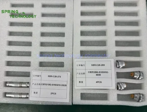


CBTG3BG Push-Pull Connector for Arc-Welding Controller Cabinets 2026: 3B Series 16-Contact 8 A Plug and Mating Receptacle for Welding Robot Control
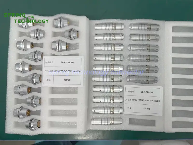
The CBTG3BG-SMSM16-D92B and CBME3BG-SFSM16-S000 are CBTG3BG push-pull connectors for arc-welding controller cabinets — a 3B series 16-contact plug rated up to 8 A with AWG 30–22 conductor support, IP50 protection, cable jacket compatibility of 7.8–9.2 mm and shielding of at least 75 dB at 10 MHz, paired with its specified mating fixed receptacle. Every specification in this guide is backed by the welding automation interconnect engineering of Spring Technology.
Pain point: Wiring a robotic welding controller cabinet — where control signals, wire-feeder status, sensor feedback, interlocks and auxiliary circuits all route between internal modules and external equipment on a cell full of servo drives, welding sources and moving arms?
Core answer: Spring Technology supplies the CBTG3BG-SMSM16-D92B plug and its specified mating receptacle, which can be evaluated for multi-contact control and auxiliary power interfaces where secure locking, compact wiring and mechanical durability are important. An industrial robotic arc-welding system typically includes a robot controller, welding power source, wire feeder, torch control unit, position sensors and safety circuits, with the controller cabinet connecting these subsystems and coordinating their operation throughout the welding process. Where the electrical design and mating interface are compatible, this connector type suits multi-circuit connections between a robotic welding controller cabinet and its auxiliary modules.
1. Technical Parameters & Engineering Standards
This CBTG3BG push-pull connector for arc-welding controller cabinets is built on the 3B series push-pull platform, a low-voltage circular connector family for industrial control equipment.
- Latching Mechanism: Push-pull self-latching mechanism (quick mating and release without repeatedly turning a threaded coupling)
- Recommended Hardware: Spring Technology Circular Connector
- Key Metric: 16 contacts; up to 8 A; IP50; up to 5,000 mating cycles
| Parameter | Value |
|---|---|
| Plug (this order) | CBTG3BG-SMSM16-D92B — TG plug, 3B shell, key G, 16 contacts |
| Mating receptacle | CBME3BG-SFSM16-S000 — specified mating fixed receptacle (designation to be verified before order) |
| Contacts | 16 low-voltage contacts |
| Rated current | Up to 8 A |
| Conductor size | AWG 30–22, up to 0.34 mm² |
| Termination | Solder termination |
| Cable diameter | Jacket approx. 7.8–9.2 mm |
| Protection | IP50 (protected indoor environments) |
| Shielding | Min. 75 dB at 10 MHz, 40 dB at 1 GHz |
| Mating cycles | Up to 5,000 mating cycles |
| Shock resistance | Up to 100 g |
| Vibration resistance | 15 g over 10–2000 Hz |
Note: ratings apply to compatible auxiliary and control circuits. The connector should not be assumed suitable for carrying welding current or the main power output of a welding source.
2. Arc-Welding Controller Connector Design Highlights
Welding cells combine high currents, moving machinery and EMC pressure. The design considerations below explain why this CBTG3BG push-pull connector for arc-welding controller cabinets suits controller cabinet interfaces:
2.1 Sixteen Contacts for Multi-Circuit Control Connections
- A robotic welding controller coordinates control signals, operating status, sensor feedback and auxiliary circuits. Sixteen low-voltage contacts in one interface let designers consolidate multiple compatible circuits into a single cable connection instead of several separate connectors — covering robot controller auxiliary I/O, welding process control signals, wire feeder status and control, sensor feedback, auxiliary module interfaces and equipment interlock signals. The actual contact assignments must follow the controller’s electrical schematic, and safety-critical circuits should use an appropriately designed and validated safety architecture.
2.2 Push-Pull Locking for Faster Maintenance
- Robotic welding equipment requires cable replacement, controller servicing and production-line maintenance. The push-pull self-latching mechanism allows quick mating and release without repeatedly turning a threaded coupling, reducing the time needed to disconnect and reconnect compatible modules. When paired with the correct panel receptacle, the connector also provides a clearly defined connection point between cabinet wiring and an external cable assembly.
2.3 Reliable Connections in Mechanically Active Environments
- Robotic welding cells operate around moving robot arms, industrial machinery and cable-management systems, so connectors must be selected for mechanical retention and repeated service. The connector is specified for up to 5,000 mating cycles with shock resistance up to 100 g and vibration resistance of 15 g over 10–2000 Hz. The connector should still be mounted and strain-relieved correctly, and cable routing must prevent robot movement from applying excessive force.
2.4 Eight-Ampere Rating for Suitable Auxiliary Circuits
- A published 8 A rated current with support for conductors up to 0.34 mm² / AWG 22 may support suitable auxiliary power circuits, depending on current distribution across contacts, ambient temperature, cable specifications and the equipment manufacturer’s electrical design. In a welding controller cabinet the connector may be considered for low-voltage auxiliary modules and control interfaces — it should not be assumed suitable for welding current or the main welding power output.
2.5 Shielding for Industrial Electrical Environments
- Welding cells contain welding power sources, servo drives, motors and other equipment that can produce electromagnetic interference. Minimum shielding performance of 75 dB at 10 MHz and 40 dB at 1 GHz supports EMC-oriented design when the connector is incorporated into a properly designed cable and grounding system. Overall performance depends on cable shield termination, enclosure bonding, wiring layout and the complete controller’s EMC requirements.
2.6 Cable Compatibility for Controller Cabinet Wiring
- Support for cable jacket diameters of approximately 7.8–9.2 mm with solder termination provides a defined cable interface for multi-contact assemblies between a controller cabinet and compatible auxiliary equipment. Before production, cable diameter, conductor size, bend radius, pin assignment and strain-relief arrangement should be checked against the actual cable assembly requirements.
3. Why Choose a Compatible 3B Push-Pull Connector Pair?
Using a compatible cable plug and fixed receptacle provides several advantages for robotic welding controller designs:
- Multi-contact integration: 16 contacts accommodate multiple compatible low-voltage circuits.
- Fast connection and release: push-pull locking simplifies routine maintenance.
- Mechanical durability: specified for repeated mating and exposure to shock and vibration.
- Shielding: specified performance supports EMC-oriented cable design.
- Defined cable interface: the cable collet accommodates a specified jacket diameter range.
- Panel integration: a compatible fixed receptacle provides a structured connection point on the controller cabinet.
Plug and receptacle must have matching series, size, keying, contact configuration and mechanical dimensions — the exact CBME3BG-SFSM16-S000 designation should be verified before treating it as the confirmed mating part.
4. 3B Series Connector Family Overview
The 3B shell is part of Spring Technology’s push-pull connector family for industrial and professional equipment: the same platform serves this CBTG3BG push-pull connector for arc-welding controller cabinets and other control applications across plugs, fixed receptacles and cable assemblies.
4.1 Available Configurations
- Connectors: 3B series plugs (including this order), fixed receptacles and related cable assemblies.
- Contact layouts: multi-contact low-voltage configurations, including the 16-contact version used here.
- Termination: solder termination with cable collet and defined jacket range.
- Coupling: push-pull self-latching with keying to prevent mismating.
4.2 Customization Services
- Custom contact allocations and part numbers (such as the CBTG3BG-SMSM16-D92B) matched to each controller’s schematic.
- Multi-contact control cable assemblies sized to the cabinet and cell routing.
- Mating receptacle selection support, including verification of series, size, keying and contact configuration.
- Shielding and EMC verification for cable and grounding design.
5. Applications: Robotic Arc-Welding Controller Cabinets
The plug and a verified compatible panel receptacle can be evaluated for the following equipment types in this CBTG3BG push-pull connector for arc-welding controller cabinets application:
5.1 Controller Cabinets and Auxiliary Control Modules
Industrial robotic arc-welding controller cabinets and welding robot auxiliary control modules.
5.2 Cell I/O Panels and Feeder Interfaces
Robotic welding cell I/O panels, welding wire feeder control interfaces and welding torch monitoring modules.
5.3 Production-Line Control and Service Panels
Automated welding production-line control systems and robotic welding equipment service panels.
6. Frequently Asked Questions (FAQ)
Conclusion & Call to Action
This 3B connector delivery shows how Spring Technology serves welding automation — from the 16 contacts and 8 A rating of the CBTG3BG-SMSM16-D92B to its shielding and defined cable interface, every detail was aligned with the customer’s robotic arc-welding controller cabinet requirements. Spring Technology also provides professional customization services for both push-pull connectors and cable assemblies, offering tailored solutions to meet your specific technical requirements.
For more information about our push-pull circular connectors or to discuss your requirements, contact us at [email protected] or [email protected], or visit our website.
Building a robotic welding cell or controller cabinet? Send us your schematic and cable requirements — our engineering team will respond with a tailored CBTG3BG push-pull connector proposal for your arc-welding controller cabinets within 24 hours.
Further Reading
- CBTG2BG Push-Pull Connector for Industrial Robot Controllers 2026: 2B Series 19-Pin Connector for Robot Control Cabinets for US Client
- Push-Pull Connector for Industrial Robotics 2026: CBZC0BG-SFSM04, CBZC0BG-SFSM06 and CBTE0BG-SMSM06 for High-Precision Test, Measurement and Industrial Robotics for Russian Customers
- Push-Pull Connector for Control Cabinets 2026: CBTG2BG-SMSM02-D52B and CBME2BG-SFSM10-0000 for Advanced Industrial Automation and Robotics Control Cabinets for Russian Customers
- Push-Pull Connector for Robot Control Panels 2026: CBTG2BG-SMSM08-D990 for Heavy-Duty Teach Pendants and Control Panels for Canadian Distributor
- MHF.3B.872.CLL 3B Operating Table Connector: 13-Contact Push-Pull Receptacle for Medical Equipment
- TGF.3B.872.CLAD32Z & BFF.3B.1250.CSN (250pcs) to USA 2026: 13-Contact Latching Push-Pull Plug with Dust Cap for Medical Equipment | 3B Series Case Study
- Push-Pull Circular Connectors — Product Range