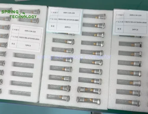


K Series Receptacles for ROV Inspection Electronics 2026: 1K and 2K Four-Contact Panel Sockets in ZG and MG Bodies
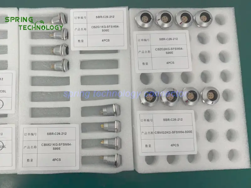
The CBZG1KG-SFSM04-S00E, CBMG1KG-SFSM04-S00E, CBZG2KG-SFSM04-S00E and CBMG2KG-SFSM04-S00E are K series receptacles for ROV inspection electronics — four-contact panel sockets in 1K and 2K shell sizes across the ZG and MG receptacle bodies, with IP68/IP66 protection when mated, nut fixing and keying, push-pull connection, 2–16 pins (1K) or 2–26 pins (2K) across the range, operation from -45 °C to +125 °C and more than 5,000 mating cycles, with M16 panel drill holes on the 1K bodies and M20 on the 2K bodies. Every specification in this guide is backed by the subsea equipment interconnect engineering of Spring Technology.
Pain point: Fitting a sealed, serviceable interface into an ROV electronics enclosure — where modules are swapped between deployments, the 1K and 2K sizes carry different current ratings and panel cutouts, and no connector rating can be assumed to suit every immersion depth?
Core answer: Spring Technology offers these four-contact receptacle models for evaluation in suitable low-voltage interfaces in ROV inspection electronics, supporting four-contact connectivity, push-pull interfaces and panel integration for underwater equipment design. Remotely operated vehicles inspect underwater infrastructure including pipelines, harbor structures, offshore platforms and offshore wind foundations, and depending on the mission an ROV may carry cameras, lighting systems, sonar equipment, navigation sensors and specialized inspection tools. These components rely on an electronic system that distributes suitable power and control signals and connects compatible modules, with panel-mounted connectors providing defined electrical interfaces between an electronics enclosure and detachable equipment or cable assemblies. The appropriate choice depends on the enclosure design, electrical requirements, environmental exposure and exact connector specifications — and these receptacles should not be assumed interchangeable or suitable for direct underwater exposure without verifying the exact model and its environmental rating.
1. Technical Parameters & Engineering Standards
All four models are K series panel receptacles with four low-voltage contacts, offered in two shell sizes and two receptacle bodies.
- Latching Mechanism: K series push-pull self-latching connection system (with a compatible mating plug, no repeated threaded-coupling rotation)
- Recommended Hardware: Spring Technology Circular Connector
- Key Metric: 4 low-voltage contacts; IP68/IP66 (mated); M16 or M20 panel drill hole; >5,000 mating cycles
1.1 The Four Models Compared
| Model | Shell / body | Contacts | Published rated current | Panel drill hole |
|---|---|---|---|---|
| CBZG1KG-SFSM04-S00E | 1K — ZG panel socket | 4 | 10 A | M16 |
| CBMG1KG-SFSM04-S00E | 1K — MG panel socket | 4 | Confirm per exact model | Confirm per exact model |
| CBZG2KG-SFSM04-S00E | 2K — ZG panel socket | 4 | 15 A | M20 |
| CBMG2KG-SFSM04-S00E | 2K — MG panel socket | 4 | Confirm per exact model | Confirm per exact model |
1.2 Shared K Series Platform Specifications
| Parameter | Value |
|---|---|
| Series | K series — 1K and 2K shell sizes, ZG and MG receptacle bodies |
| Protection | IP68/IP66 (mated) |
| Pin counts available | 2–16 pins (1K) / 2–26 pins (2K) |
| Termination | Solder |
| Mounting | Fixed panel receptacle with nut fixing |
| Sealing | Watertight or vacuumtight constructions available across the range |
| Operating temperature | -45 °C ~ +125 °C |
| Vibration resistance | 10~20000 Hz, 15 g |
| Shock resistance | 100 g · 6 ms |
| Mating cycles | >5,000 cycles |
| Keying | Standard key G; alternative keys A…F, L and R according to body |
Note: the current ratings must be applied according to the manufacturer’s derating guidance and the complete circuit design and should not be interpreted as a guarantee that all contacts can continuously carry the maximum rated current simultaneously under every operating condition.
2. Connector Design Highlights for ROV Inspection Equipment
ROV electronics are sealed, serviced and redeployed. The design advantages below explain why these K series receptacles for ROV inspection electronics suit subsea panel interfaces:
2.1 Four Contacts for Compact Electrical Interfaces
- All four models use a four-contact, low-voltage configuration, accommodating multiple electrical circuits within one connector depending on the equipment’s wiring design. For an ROV electronics module, potential functions include compatible auxiliary power, control signals, status signals or other low-voltage connections — combining suitable circuits in one interface organises wiring and reduces the number of separate connection points. The contact assignment must be established by the system designer, since contact count alone does not establish compatibility with a specific camera, sonar, sensor or communication protocol.
2.2 Push-Pull Connection for Equipment Servicing
- The K series uses a push-pull self-latching connection system. With a compatible mating plug, this mechanism supports convenient connection and release without repeatedly rotating a threaded coupling. ROV electronics may require inspection, cable replacement or module servicing between deployments, so a suitable quick-release interface helps technicians manage connections during maintenance and equipment configuration changes. The exact mating plug must be selected according to the receptacle’s series, size, keying, contact configuration and model-specific requirements.
2.3 Panel-Mount Integration for Organized Enclosures
- The ZG models are fixed, front-mounted panel receptacles providing a defined connection point on a compatible equipment enclosure. In ROV electronics, a dedicated panel interface helps separate external cable connections from internal wiring and makes the interface more accessible during servicing; the panel layout should be designed around the required mounting dimensions, cable routing and mechanical clearances. The MG models are also receptacle-style connectors, and their precise sealing configuration should be confirmed for the exact part number before assigning them a particular environmental advantage.
2.4 Different Connector Sizes for Different Electrical Designs
- The 1K and 2K sizes offer different mechanical and electrical configurations: the 1K model is published at a rated current of 10 A with an M16 panel drill hole, and the 2K model at 15 A with an M20 panel drill hole. These differences let engineers evaluate the connector size against enclosure space, conductor requirements and electrical load.
2.5 Environmental Protection for Suitable Equipment Interfaces
- The published specifications list IP68/IP66 protection (mated) for the ZG models, making them candidates where the manufacturer’s specified environmental protection is required. However, an IP rating applies under defined test conditions and does not automatically establish suitability for every underwater installation, pressure depth or duration of immersion — the enclosure, cable assembly, mating connector, seals and installation procedure must also meet the application requirements. For the MG models, verify the exact product documentation before claiming a specific sealing performance, and do not transfer specifications from variants with additional suffixes to the unsuffixed models without confirmation.
2.6 Support for Maintainable Modular Equipment
- An ROV may use replaceable electronics modules or configurable inspection payloads, and a properly designed detachable connection simplifies servicing and helps technicians restore the system after maintenance. A panel receptacle provides a defined interface for compatible cable assemblies and supports a more organised enclosure design — with the overall maintenance benefit depending on the ROV’s architecture, access to the electronics, cable routing and the connector’s suitability for the operating environment.
3. Comparing the 1K and 2K Receptacle Options
The 1K and 2K models differ in connector size and published electrical ratings: the 1K ZG model has an M16 panel drill hole and a 10 A rated current, while the 2K ZG model has an M20 panel drill hole and a 15 A rated current. The ZG and MG designations also represent different receptacle constructions and should not be treated as direct substitutes without checking their mounting, sealing and mating requirements.
Before choosing any of the four models, confirm:
- The exact product number and current manufacturer datasheet
- Compatibility with the intended mating plug, including keying and contact arrangement
- Panel drill hole, mounting dimensions and available enclosure space
- Operating voltage, current, conductor size and circuit assignment
- Environmental sealing requirements for the intended water depth and operating duration
- Cable assembly, grounding, shielding and strain-relief requirements
4. K Series Connector Family Overview
The K series belongs to Spring Technology’s push-pull connector family for sealed underwater and industrial equipment. The same platform serves these K series receptacles for ROV inspection electronics and scales across 1K and 2K shells, ZG and MG receptacle bodies and contact counts.
4.1 Available Configurations
- ZG bodies (ZGG): 1K and 2K fixed panel sockets with M16 and M20 panel drill holes respectively.
- MG bodies (MGG): 1K and 2K fixed panel sockets with nut fixing and watertight or vacuumtight constructions.
- Pin counts: 2–16 contacts (1K) and 2–26 contacts (2K), including the four-contact layouts listed here.
- Keying: standard key G with alternative keys A…F, L and R according to body to prevent mismating.
4.2 Customization Services
- Custom contact allocations and part numbers (such as the four models listed here) matched to each system’s circuit plan.
- Sealing configuration support for watertight or vacuumtight requirements.
- Cable assembly builds matched to the mating plug and enclosure layout.
- Mating plug selection support, including keying and contact-layout confirmation.
5. Applications: Subsea Inspection Electronics
These are potential engineering applications for these K series receptacles for ROV inspection electronics, based on the connector configuration — not verified installations in specific vehicle brands or models:
5.1 ROV Inspection Electronics and Sensor Interface Modules
Panel interfaces in ROV inspection electronics enclosures and subsea sensor interface modules.
5.2 Underwater Infrastructure Inspection
Equipment used to inspect pipelines, harbor structures, offshore platforms and offshore wind foundations.
5.3 Modular Inspection Payloads
Detachable cable and module interfaces for cameras, lighting systems, sonar equipment and inspection tools.
6. Frequently Asked Questions (FAQ)
Conclusion & Call to Action
This K series delivery shows how Spring Technology serves subsea inspection equipment — from the M16 10 A 1K sockets to the M20 15 A 2K sockets, across both ZG and MG receptacle bodies with IP68/IP66 mated protection, every detail was aligned with the customer’s ROV inspection electronics requirements. Spring Technology also provides professional customization services for both push-pull connectors and cable assemblies, offering tailored solutions to meet your specific technical requirements.
For more information about our K series connectors or to discuss your requirements, contact us at [email protected] or [email protected], or visit our website.
Building an ROV electronics enclosure or subsea sensor module? Send us your depth, circuit and panel requirements — our engineering team will respond with a tailored K series receptacles proposal for your ROV inspection electronics within 24 hours.
Further Reading
- CBME2CG Push-Pull Connector for ROV Thruster Systems 2026: 2C Series 3-Contact IP68 Panel Socket for Underwater Vehicles
- Push-Pull Connector for Subsea Drones 2026: CBTG2CG-SMSM03-D92B and CBME2CG-SFSM03-S000 for Remotely Operated Vehicles and Subsea Drones for Russian Customers
- Push-Pull Connector for Underwater Equipment 2026: CBG82FN-TFS650-S000 Hermetic Socket for Rugged Underwater Testing Tools for Pakistani Client
- Push-Pull Connector for Oceanographic Sensors 2026: CBTG1CB-KMSM04-D52B Plug for Oceanographic Sensor Umbilicals for Indian Customers
- TVN.105F & MLN.105F 105F Underwater Connector: Thread-Lock Connectors Successfully Used in Underwater Conditions | Customer Feedback
- ZGG 1K Fixed Socket — Product Page
- ZGG.2K Fixed Socket — Product Page
- MGG 1K Fixed Socket — Product Page
- K Series Connector