How to choose connectors for hardware design
The design of electronic products tends to be more and more modular. The combination of different functional modules can quickly create high-quality products with different performances, and the connection of the modules is particularly important. The connector is like a functional interface of the program. Reasonable, in the future product maintenance, upgrades, and transplants will do more with less, so that the product maintains lasting vitality; unreasonable design, causing difficulties in future maintenance and upgrades, which will affect the whole body, and ultimately make the product lose its competitiveness. The importance is self-evident.
The connector, also known as the connector commonly used by engineers, is used to connect two circuit boards or electronic devices to realize the transmission of power or signals. Through the connector, the circuit can be modularized, the assembly process of the electronic product is simplified, and the product is easy to maintain and upgrade.
There are many types of connectors. Common types include communication interface terminals, wiring terminals, wire-to-board connectors, board-to-board connectors, etc. Each category can be subdivided into several categories, such as:
Board-to-board connectors include pin headers, PC104, board-to-board connectors, etc.;
Wire-to-board connectors include FPC connectors, IDC sockets, and simple horn seats.
For modular circuits, connector selection plays a decisive role, so when choosing connectors, from what angle should we consider suitable connectors for hardware?
1. Pins and pitch
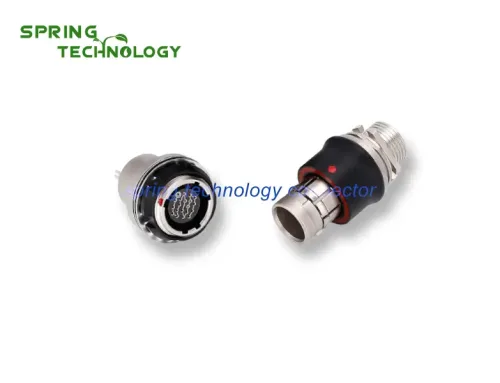
The number of pins and the pitch of pins are the basic basis for connector selection. The number of pins selected depends on the number of signals to be connected. For some SMD connectors, as shown in the following figure, the number of pins should not be too many. Because during the soldering process of the placement machine, due to the effect of high temperature, the connector plastic will be deformed by heat, and the central part will swell, resulting in virtual soldering of the pins. Our P800Flash programmer used this pin header and pin header to make board-to-board connection in the early stage of development. As a result, the pins of the prototype pin header were soldered in large areas. After replacing the two pin headers with the number of pins halved, no virtual soldering occurred.
Nowadays, electronic equipment is developing toward miniaturization and precision, and the pin pitch of the connector is also from 2.54mm to 1.27mm to 0.5mm. The smaller the lead pitch, the higher the production process requirements. The lead pitch should be determined by the company’s production process level. Blindly pursuing small pitch will cause difficulties in production and maintenance.
2. Electrical performance
The electrical properties of the connector mainly include: limit current, contact resistance, insulation resistance and electric strength. When connecting a high-power power supply, pay attention to the limit current of the connector; when transmitting high-frequency signals such as LVDS, PCIe, etc., pay attention to the contact resistance. The connector should have a low and constant contact resistance, generally tens to hundreds of mΩ.
3. Environmental performance
The environmental performance of the connector mainly includes: temperature resistance, humidity resistance, salt spray resistance, vibration, impact and so on. Choose according to the specific application environment. If the application environment is relatively humid, the requirements on the connector’s resistance to moisture and salt spray are high to avoid corrosion of the metal contacts of the connector. In the field of industrial control, the anti-vibration impact performance of the connector is high, so as to avoid the connector falling off during the vibration process.
4. Mechanical properties
The mechanical properties of the connector include pulling force, mechanical foolproofing, etc. Mechanical foolproofing is very important to the connector. Once it is inserted reversely, it may cause irreversible damage to the circuit!
The insertion force is divided into insertion force and separation force. The relevant standards stipulate the maximum insertion force and the minimum separation force. From the perspective of use, the insertion force should be small and the separation force should be large. Too small separation force will reduce the reliability of contact, but for connectors that often need to be plugged and unplugged, too much separation force will increase the difficulty of extraction and reduce the mechanical life.
Xi’an spring technology Co., Ltd. is a professional push pull connector manufacturer integrating connector research and development, production and sales.
Contact me for more info and best price: [email protected], [email protected]
Visit our website: https://www.spring-connectors.com/