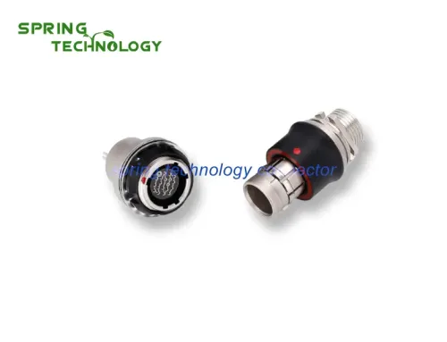
Comprehensive analysis of electrical connectors in signal applications
Connectors are used to transmit signals and power. There are some differences between these applications. The two most important differences are the current / voltage application and the temperature rise of the connector.
Regarding current and voltage, current is often used as a signal application, but using voltage is more common, which is more “low power”. For example, an application current of less than 1 ampere is generally regarded as a signal application, and a current of more than 10 amperes is regarded as a power application. However, this “definition” is very limited. For example, for small connectors, the current flow rate is 1 ampere or less. This is due to the contact cross section. This contact will raise the temperature by 1 ampere. This will lead to the second difference. The temperature rises.
There is usually a standard that treats temperature rise (T rise) to 30 ° C as energization. Although this standard is arbitrarily formulated, it is indeed based on insurance companies’ guidance on the safety of household appliances. In this discussion, the temperature rise (T rise) will be used to judge the current speed standard. However, depending on the application requirements, a higher temperature rise (T rise) can still be accepted. According to this standard, if the relevant temperature rise (T rise) is less than 10 ° C, it is regarded as a signal application; if the temperature rise is greater than 20 ° C, it is regarded as an electrical application.
For power supply applications, current / voltage and temperature rise (T rise) standards are important. However, whether they are particularly important for signal applications remains controversial. There is another set of criteria, that is, the frequency of current / voltage is more important for the application of signal connectors. Signal applications will be discussed in the context of frequency.
Comprehensive analysis of electrical connectors in signal applications
In signal applications, the focus of signal applications will be to maintain the integrity of the signal-especially the signal’s rise time and waveform. For power applications, the result of connector power distribution is to find the minimum parameter value of the most relevant current in the system.
1 Signal application
The application of signal connectors is the transmission of current or voltage waveforms between two points. In addition to the fact that there is no unacceptable loss in gain or frequency, the shape and waveform of the gain must also be maintained. Either way, the waveform is unacceptable. Because the amplitude of these voltages and currents is usually relatively large and low (in large-signal applications, the typical voltage is a few volts and a few milliamperes), through mutual communication will cause some attenuation, which is very harmful. The characteristics of signal connectors can lead to two broad topics, namely signal transmission quality (STQ) and electromagnetic compatibility (EMC).
Signal transmission quality (STQ) refers to high-speed signal transmission without unacceptable peaks caused by loss of signal waveforms in connectors and interconnected systems. Loss components include crosstalk, value-added delays, and the results of characteristic impedance fluctuations related to signal propagation and reflection. STQ refers to the protection of the transmission and required signal waveforms in electronic systems.
On the other hand, EMC focuses on eliminating or compatible with external electromagnetic waves, noise and interference to prevent signal attenuation. When EMC is detected in an interactive communication device, measures such as shielding, filtering, and grounding will be used to control electromagnetic interference (EMI) and radio frequency interference (RFI), which together constitute EMC.
The signal application can be analog or digital. The application of analog quantity needs special attention to the waveform, because the waveform is essentially a transmission signal. As long as the waveform is uniform, a slight loss of waveform amplification can be allowed. As is well known, crossover frequency boundaries are included in the waveform. If either of the two standards is missing, the signal will be distorted.
In this discussion, the reason for focusing on digital signal applications is that for digital applications, connectors are usually more urgent than for analog applications. In digital applications, signal frequency has a decisive influence on connector requirements and design considerations.
The above frequency includes two aspects: the frequency of the signal pulse, the time pulse of the day and the rise time frequency of the pulse itself. Generally, the pulse rise time will be used as the dominant factor because the frequency of the fast rise pulse is higher than the frequency of the clock pulse. Its maximum frequency value Vm, pulse rise time Tγ can be approximately expressed as:
Vm = 0.35 / Tγ
Corresponding to the rise time of 1 nanosecond, the maximum frequency is 350MHZ, which exceeds the typical clock frequency. In the 160 MHZ personal computer order with a history of 1996, the pulse rise time will be used as an important consideration. In this case, the connector must be able to transmit a non-attenuating pulse waveform, and the pulse waveform includes considerations including rise time and voltage / amplitude. When the size of the connector is equivalent to the length of the electronic pulse, the signal application will depend on these considerations. In other words, under these conditions, the connector can be regarded as a transmission channel. There are many ways to choose the appropriate electromagnetic wave length to make this decision. The method used in this discussion is related to the size of the connector and the rise length of the pulsed electromagnetic wave. The length of the pulsed electromagnetic wave rise is the distance of the signal from zero to full voltage along the conductor. Given the following formula:
Lr = Vp & TImes; Tγ
The signal propagation speed is given by the following formula:
Vp = C (εeff) 1/2
Where C = speed of light
εeff = effective dielectric constant of the propagation medium
The effective dielectric constant takes into account changes in the composition of the material, such as the geometry of the air polymer in the foam insulator or connector / air cavity of the insulator. In this case, a proper average value of a single dielectric constant is necessary.
The main idea in this discussion is that in the direction of signal transmission, the length of the connector is greater than 0.3Lr, and the connector can be regarded as a transmission channel. For connectors and printed circuit boards, a suitable effective dielectric constant value is about 4. Respectively, for pulses with rise times of 1 and 10 nanoseconds, respectively, the critical lengths of the components are 2 and 202, respectively.
According to this standard, it is obvious that the length of printed circuit boards and cables is usually 10/8, which should be regarded as a transmission channel for pulses greater than 10 nanoseconds. In fact, in recent years, design rules for transmission channels have been applied to PWBs and cables. On PWB and controllable impedance cables, the geometry is usually microblocks and microstrips. In the prior art, when the signal rise time exceeds the specification of less than 10 nanoseconds, the connector must be regarded as a signal transmission channel. In such applications, transmission channel parameters (such as characteristic impedance and crosstalk) will replace contact resistance, which is a “critical” performance consideration.
2 The basis of the transmission channel
Before discussing the transmission channel, let us briefly discuss the sequential propagation of electromagnetic waves. Electromagnetic waves are composed of two areas perpendicular to each other. The equivalent relationship of wave characteristics is as follows:
C = λυ
Where C = speed of light in vacuum
λ = wavelength
υ = wave frequency
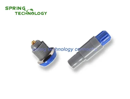
Xi’an spring technology Co., Ltd. is a professional push pull connector manufacturer integrating connector research and development, production and sales.
Contact me for more info and best price: [email protected], [email protected]
Visit our website: https://www.spring-connectors.com/