

Introduction: Understanding Connector Fundamentals for Modern Applications
Connectors form the backbone of modern electrical and electronic systems, enabling reliable signal transmission across diverse applications from consumer electronics to aerospace defense. As we advance through 2026, the global connector market continues its robust expansion, projected to reach $115 billion by 2027 with a CAGR of 5.8% from 2024-2027, driven by 5G infrastructure deployment, electric vehicle adoption, industrial automation, and emerging IoT applications.
This comprehensive guide explains fundamental connector terminology, technical definitions, and industry standards essential for engineers, procurement specialists, and technical decision-makers. Whether you are selecting RF connectors for communication systems, coaxial connectors for measurement equipment, or hermetic connectors for harsh environments, understanding these basic concepts ensures informed component selection and reliable system performance.

1. Connector Fundamentals and Definitions
1.1 What is a Connector?
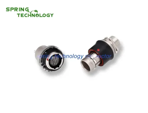
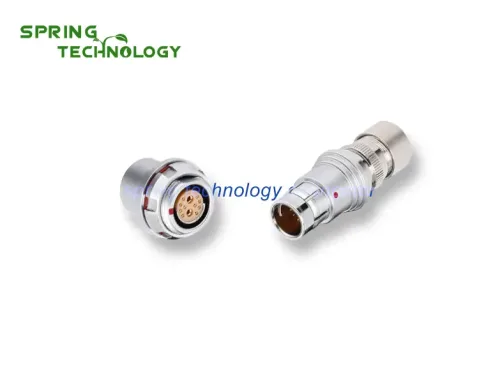
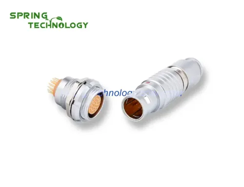
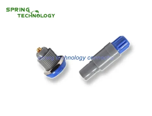
Connector: A detachable element (except for adapters) usually installed on cables or equipment for electrical connection of transmission line systems. Connectors enable modular system architecture, facilitating assembly, maintenance, and component replacement without permanent soldering or wiring modifications.
Key connector characteristics include:
- Mechanical Interface: Physical coupling mechanism (threaded, bayonet, push-pull, snap-on)
- Electrical Contacts: Conductive elements (pins, sockets, PCB tails) for signal/power transmission
- Insulation: Dielectric materials separating contacts to prevent short circuits
- Housing: Protective shell providing environmental sealing and mechanical support
1.2 RF Connector Definition
RF Connector: A connector specifically designed for use in the radio frequency range, typically from DC to microwave frequencies (up to 110 GHz for precision connectors). RF connectors maintain controlled impedance (commonly 50Ω or 75Ω) and minimize signal reflection, insertion loss, and electromagnetic interference across operating frequencies.
Common RF connector families include:
- SMA, SMB, SMC: Subminiature connectors for frequencies up to 18-24 GHz
- N-Type: Medium-power RF connector up to 11 GHz
- TNC, BNC: Bayonet coupling for quick-disconnect applications
- 7/16 DIN: High-power connector for cellular base stations
- 2.92mm, 2.4mm, 1.85mm: Precision connectors for millimeter-wave applications
2. Frequency Range Classifications
2.1 Video Frequency Range
Video: Radio waves with a frequency range of 3Hz to 30MHz. This range encompasses baseband video signals, audio frequencies, and low-frequency control signals. Connectors for video applications prioritize shielding effectiveness and impedance matching to prevent signal degradation.
2.2 Radio Frequency Spectrum
Radio Frequency (RF): Radio waves with a frequency range of 3,000Hz (3kHz) to 3,000GHz (3THz). The RF spectrum is subdivided into multiple bands for different applications:
- LF (Low Frequency): 30kHz – 300kHz, navigation, time signals
- MF (Medium Frequency): 300kHz – 3MHz, AM radio broadcasting
- HF (High Frequency): 3MHz – 30MHz, shortwave radio, amateur radio
- VHF (Very High Frequency): 30MHz – 300MHz, FM radio, television, two-way radio
- UHF (Ultra High Frequency): 300MHz – 3GHz, mobile phones, WiFi, GPS, Bluetooth
- SHF (Super High Frequency): 3GHz – 30GHz, satellite communications, radar, 5G
- EHF (Extremely High Frequency): 30GHz – 300GHz, millimeter-wave 5G, automotive radar
2.3 High Frequency Definition
High Frequency (HF): Radio waves with a frequency range of 3MHz to 30MHz. HF communications leverage ionospheric reflection for long-distance propagation, making this band critical for maritime communications, aviation, amateur radio, and international broadcasting.
3. Transmission Line Structures
3.1 Coaxial Transmission Lines
Coaxial: A transmission line structure where the inner conductor has dielectric support, and the outer conductor surrounds it concentrically. This configuration provides excellent shielding, controlled impedance, and minimal signal radiation. Coaxial connectors obtain the smallest internal reflection coefficient in the frequency range used for measurement applications.
Coaxial connector advantages:
- Shielding Effectiveness: >90 dB attenuation of external electromagnetic interference
- Impedance Control: Precise 50Ω or 75Ω characteristic impedance
- Wide Bandwidth: DC to millimeter-wave frequencies (up to 110 GHz)
- Low Loss: Minimal signal attenuation across transmission path
3.2 Triaxial Transmission Lines
Triaxial: A transmission line composed of three layers of concentric conductors with a common axis, insulated from each other. The additional outer conductor provides enhanced shielding and enables differential signal transmission or guarded measurement circuits.
Triaxial applications include:
- Low-Level Signal Measurement: Picoammeters, electrometers, sensitive scientific instruments
- Differential Signaling: Noise-canceling circuits for high-interference environments
- High-Voltage Testing: Guarded measurements to eliminate leakage currents
4. Connector Performance Grades
4.1 Grade Classification System
Grade: The classification level of a connector in terms of mechanical and electrical precision, especially regarding the specified reflection coefficient (VSWR). Connector grades define performance tiers from commercial-grade to laboratory precision standards.
4.2 Universal Connector (Grade 2)
Universal Connector (Level 2): A connector manufactured with the widest allowable dimensional deviation (tolerance) while still guaranteeing minimum specified performance and interoperability.
Note: The requirements for reflection coefficient may or may not be specified for Grade 2 connectors. These connectors are suitable for general-purpose applications where cost-effectiveness is prioritized over precision performance.
4.3 High-Performance Connector (Grade 1)
High-Performance Connector (Level 1): A connector that specifies the limit value of the reflection coefficient according to frequency changes. Generally, the specified dimensional tolerance is not stricter than the corresponding Grade 2 connector, but it must ensure that the connector meets reflection coefficient requirements across the operating frequency range.
When reflection coefficient performance is critical, the manufacturer is responsible for choosing tighter tolerances to maintain consistent electrical performance. Grade 1 connectors are specified for communication systems, test equipment, and applications requiring predictable RF performance.
4.4 Standard Test Connector (Grade 0)
Standard Test Connector (Level 0): A specific type of precisely manufactured connector used to measure the reflection coefficient of Grade 1 and Grade 2 connectors. The error caused by measurement results can be ignored due to exceptional dimensional accuracy and electrical performance.
Note: The standard test connector is typically part of the adapter between different connector types. The connection between the adapter and precision connector forms part of the test equipment calibration chain. Grade 0 connectors are essential for metrology laboratories and connector manufacturing quality control.
5. Sealing and Environmental Protection
5.1 Hermetic Connectors
Hermetic Connector: A connector that meets specified gas, moisture, or liquid tightness requirements. Hermetic connectors prevent environmental ingress that could cause corrosion, electrical leakage, or signal degradation in harsh operating conditions.
Hermetic connector applications:
- Aerospace: Pressurized cabin systems, avionics enclosures
- Medical: Implantable devices, sterilizable equipment
- Underwater: Subsea instrumentation, ROV systems
- Industrial: Chemical processing, oil/gas exploration
5.2 Barrier Seals
Barrier Seal: A seal that prevents gas, moisture, or liquid from entering the connector housing along the axial direction (through the cable entry point). Barrier seals typically employ O-rings, compression gaskets, or potting compounds to create environmental barriers.
5.3 Panel Sealing
Panel Sealing: Prevents gas, moisture, or liquid from entering the seal between the fixed or adapter housing and the panel through the mounting hole. Panel seals utilize mounting flange gaskets, O-ring grooves, or thread sealants to ensure equipment enclosure integrity.
5.4 Mating Surface Seals
Mating Surface Seal: A seal designed to prevent gas, moisture, or liquid from entering the interface of a pair of mating connectors. These seals typically incorporate elastomeric O-rings or gaskets compressed during connector mating to create environmental barriers at the coupling interface.
5.5 Hermetic Seal Testing
Hermetic Seal: A seal meeting the requirements of test Qk in IEC 60068-2-17 “Basic Environmental Test Procedure Part 2: Test Q: Sealing.” This standardized test verifies connector leakage rates under specified pressure differentials, ensuring compliance with military, aerospace, and medical device standards.
Note: Seals are usually provided as separate components or integrated into connector designs based on application requirements. Proper seal selection and installation are critical for maintaining environmental protection throughout the connector service life.
6. 2026 Connector Industry Trends
6.1 High-Speed Digital Integration
Modern connectors increasingly support both RF and high-speed digital signals in unified platforms. USB4, Thunderbolt 4, and PCIe 5.0 connectors operate at frequencies exceeding 20 GHz, blurring traditional boundaries between RF and digital interconnection technologies.
6.2 Miniaturization and Density
Equipment miniaturization drives demand for smaller connectors with higher contact density. Micro-miniature RF connectors (0.3mm to 1.0mm pitch) enable compact designs for wearable devices, implantable medical systems, and portable test equipment without sacrificing electrical performance.
6.3 Environmental Sustainability
Connector manufacturers adopt RoHS compliance, eliminate hazardous materials (cadmium, hexavalent chromium), and implement recyclable materials. Sustainable manufacturing practices and circular economy principles increasingly influence connector design and end-of-life considerations.
Conclusion: Mastering Connector Terminology for Informed Decisions
Understanding connector basic knowledge—from fundamental definitions to performance grades and sealing standards—empowers engineers and procurement professionals to make informed component selections. As connector technology evolves through 2026 with trends toward higher frequencies, greater miniaturization, and enhanced environmental protection, these foundational concepts remain essential for reliable system design.
Whether specifying RF connectors for 5G infrastructure, coaxial connectors for test and measurement, or hermetic connectors for harsh environments, applying these terminology standards ensures clear communication with suppliers, accurate requirement documentation, and successful project outcomes.
FAQ: Connector Knowledge Questions
Q1: What is the difference between 50Ω and 75Ω connectors?
50Ω connectors are standard for RF power transmission, two-way radio, and test equipment, optimizing power handling and low loss. 75Ω connectors are used for video signals, cable television, and digital audio, optimizing voltage transfer and minimal signal reflection for high-frequency video applications.
Q2: How do I choose the right connector grade for my application?
Grade 2 (universal) connectors suit general-purpose applications where cost is primary. Grade 1 (high-performance) connectors are specified for communication systems requiring predictable VSWR. Grade 0 (standard test) connectors are reserved for metrology laboratories and calibration standards.
Q3: What does IP67 rating mean for connectors?
IP67 indicates complete dust protection (6) and temporary water immersion resistance up to 1 meter for 30 minutes (7). This rating is common for outdoor, industrial, and marine connectors requiring environmental protection without full submersion capability.
Q4: Can RF connectors be used for DC or low-frequency applications?
Yes, RF connectors function effectively at DC and low frequencies. However, using precision RF connectors for low-frequency applications may be cost-inefficient. Standard circular connectors or terminal blocks may provide better value for non-RF applications.
Q5: What is VSWR and why does it matter?
VSWR (Voltage Standing Wave Ratio) measures impedance matching quality. Lower VSWR (closer to 1.0:1) indicates better impedance matching and less signal reflection. Typical RF connectors specify VSWR <1.2:1 or <1.5:1 depending on frequency and grade.
Extended Reading: Related Resources
- Push Pull Circular Connectors – Product Series – Spring Technology connector catalog
- Military Connectors 2026: Essential Features and Standards – Rugged connector technologies for demanding applications
- Learn to Distinguish Connectors, Terminals, and Connectors – Connector fundamentals for system design
Xi’an Spring Technology Co., Ltd. is a professional push-pull connector manufacturer integrating connector research and development, production, and sales. With extensive experience in RF, coaxial, and high-frequency connector solutions, we provide high-quality connectors for telecommunications, medical, industrial, aerospace, and test & measurement applications worldwide.
Contact us for technical consultation and pricing: [email protected], [email protected]
Visit our website: https://www.spring-connectors.com/