

Connector Basic Structure Guide 2026: Contacts, Insulators, Housing & Accessories Explained
Meta Description: Complete guide to connector basic structure in 2026. Learn about contacts, insulators, housing, and accessories. Understand how electrical connectors work, contact types, insulating materials, and connector design fundamentals.
Keywords: connector basic structure, electrical connector components, connector contacts, connector insulator, connector housing, connector accessories, push-pull connector design, connector engineering
Introduction: Understanding the Foundation of Electrical Connectivity
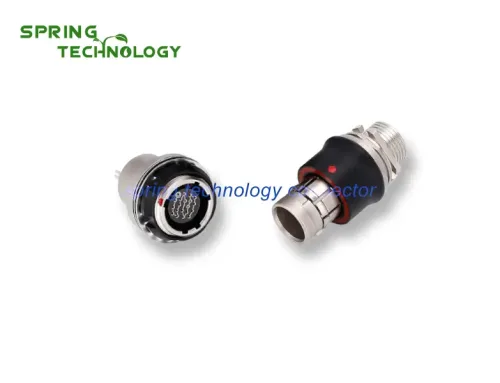
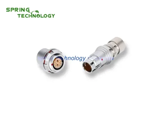
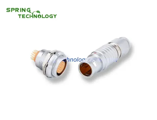
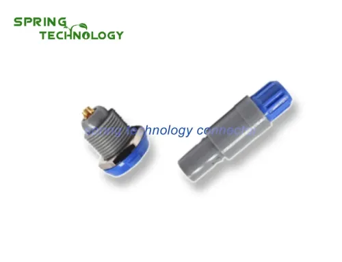
What makes a connector work? At its core, every electrical connector – from simple household plugs to sophisticated circular push-pull connectors – shares the same fundamental structural elements. Understanding these basic components is essential for engineers, technicians, and anyone working with electrical systems.
The connector industry continues to evolve, with the global market projected to reach $110 billion by 2027. Yet regardless of application – whether automotive, medical, industrial, or consumer electronics – the basic structural principles remain consistent. This guide breaks down each component and explains its critical role in ensuring reliable electrical connections.

The Four Core Components of Every Connector
1. Contacts – The Heart of Electrical Connection
Contacts are the core functional elements that complete the electrical circuit. Without properly designed contacts, a connector cannot fulfill its primary purpose.
Contact Pair Structure
Every connector relies on a contact pair system:
- Positive Contact (Male/Pin): The rigid conducting element that inserts into the mating connector
- Negative Contact (Female/Socket): The receptive element with elastic properties that grips the male contact
- Connection Mechanism: Physical insertion creates metal-to-metal contact, enabling current flow
Positive Contact Designs
Male contacts come in various geometries optimized for different applications:
- Cylindrical (Round Pin): Most common, uniform current distribution, easy to manufacture
- Square Column (Square Pin): Higher contact area, better current carrying capacity
- Flat (Blade/Plug): Space-efficient, common in automotive and consumer electronics
Material Selection
Contact materials balance conductivity, strength, and cost:
- Brass: Good conductivity and machinability, cost-effective for general applications
- Phosphor Bronze: Superior spring properties, excellent for female contacts requiring elasticity
- Beryllium Copper: Highest strength and conductivity, used in high-performance applications
- Plating: Gold, silver, or tin plating reduces contact resistance and prevents corrosion
Female Contact (Jack) Structures
The socket design determines connection reliability. Common configurations include:
- Cylindrical Type: Slotted and narrowed for spring action
- Tuning Fork Type: Two parallel beams providing balanced contact force
- Cantilever Beam: Single longitudinal slot, simple and reliable
- Folding Type: Multiple folded sections (9 shapes) for enhanced grip
- Box Shape: Square jack with four-point contact
- Hyperboloid Spring Jack: Advanced design with wire-form spring for superior reliability
2. Insulators – Ensuring Electrical Safety and Signal Integrity
Critical Functions
Insulators (also called dielectrics or inserts) serve multiple essential roles:
- Contact Positioning: Maintains precise arrangement and spacing of contacts
- Electrical Isolation: Prevents short circuits between adjacent contacts
- Contact-to-Housing Isolation: Ensures contacts don’t short to the connector shell
- Environmental Sealing: Many insulators incorporate seals for moisture protection
Material Requirements
Quality insulating materials must satisfy demanding criteria:
- High Insulation Resistance: Typically >5000 MΩ at 500V DC to prevent leakage currents
- Dielectric Strength: Withstand high voltages (1000V+ AC) without breakdown
- Thermal Stability: Maintain properties across operating temperature range (-55°C to +200°C)
- Flame Retardancy: Meet UL94 V-0 or equivalent standards for safety
- Processability: Suitable for precision injection molding with tight tolerances
- Chemical Resistance: Withstand exposure to oils, solvents, and cleaning agents
Common Insulating Materials
- Thermoplastics: PBT, PA66, PPS – cost-effective, good general properties
- High-Performance Polymers: PEEK, PEI, LCP – superior temperature and chemical resistance
- Ceramics: Alumina, steatite – extreme temperature and voltage applications
- Thermosets: DAP, BMC – excellent dimensional stability
3. Housing (Shell) – Mechanical Protection and Alignment
Primary Functions
The housing – also called the shell or body – provides the connector’s structural framework:
- Mechanical Protection: Shields internal contacts and insulator from physical damage
- Environmental Barrier: Seals against dust, moisture, and contaminants (IP67/IP68 ratings)
- Mating Alignment: Guides plug and socket into proper alignment during connection
- Device Mounting: Provides attachment points for panel or PCB mounting
- EMI/RFI Shielding: Metal housings provide electromagnetic interference protection
- Strain Relief: Anchors cables to prevent stress on electrical terminations
Housing Materials
Metal Housings
- Brass Chrome-Plated: Excellent corrosion resistance, good conductivity for shielding
- Stainless Steel: Superior strength and chemical resistance for harsh environments
- Aluminum: Lightweight, good for weight-sensitive applications
- Nickel-Plated: Enhanced corrosion resistance, non-magnetic option available
Plastic Housings
- Engineering Thermoplastics: PA, PBT – cost-effective, good dielectric properties
- Reinforced Plastics: Glass-filled variants for enhanced strength
Design Features
- Keying: Prevents mismating of similar connectors through physical coding
- Locking Mechanisms: Bayonet, push-pull, screw, or latch systems for secure mating
- Polarization: Ensures correct orientation during connection
- Threaded Coupling: M12, M16, M23 threads for panel-mount receptacles
4. Accessories – Enhancing Functionality and Installation
Structural Accessories
These components enhance connector functionality and reliability:
- Snap Rings: Secure connector assembly, prevent disassembly during use
- Positioning Keys: Ensure correct mating orientation, prevent cross-connection
- Positioning Pins: Align multiple connectors in array configurations
- Guide Pins: Facilitate blind mating by guiding connectors together
- Coupling Rings: Enable quick connect/disconnect in push-pull designs
- Cable Clamps: Provide strain relief, prevent cable pull-out
- Sealing Rings: O-rings and gaskets for IP67/IP68 environmental protection
- Gaskets: Panel-mount seals preventing moisture ingress
Installation Accessories
Hardware for mounting and securing connectors:
- Screws: Various head styles and materials for panel mounting
- Nuts: Hex nuts, locknuts for secure threaded connections
- Bolts: High-strength fasteners for demanding applications
- Spring Washers: Prevent loosening from vibration
- Mounting Flanges: Provide stable base for panel installation
- Dust Caps: Protect unused connectors from contamination
Standardization Benefits
Most connector accessories are standardized or universal parts, offering:
- Interchangeability across connector families
- Reduced inventory complexity
- Lower cost through economies of scale
- Easier maintenance and replacement
How Components Work Together: System Integration
Assembly Sequence
- Insulator Preparation: Contacts are inserted into insulator cavities
- Contact Termination: Wires are soldered or crimped to contact tails
- Housing Assembly: Insulator assembly is inserted into housing
- Accessory Installation: Seals, clamps, and hardware are added
- Final Testing: Continuity, insulation resistance, and dielectric strength verification
Performance Interdependence
Each component affects overall connector performance:
- Contact + Insulator: Determines electrical characteristics (resistance, voltage rating)
- Housing + Accessories: Defines environmental protection (IP rating, chemical resistance)
- All Components: Combined mechanical strength and mating cycle life
Industry Trends 2026: Evolution in Connector Design
Miniaturization
As devices shrink, connectors follow:
- Contact pitch decreasing to 0.5mm and below
- Higher contact density in smaller footprints
- Maintaining performance despite size reduction
High-Speed Data Transmission
Modern connectors must handle:
- Data rates exceeding 10 Gbps for camera and sensor applications
- Controlled impedance for signal integrity
- Advanced shielding to prevent EMI/RFI interference
Harsh Environment Performance
Increasing demands for:
- Extended temperature ranges (-65°C to +250°C)
- Higher IP ratings (IP68, IP69K)
- Resistance to aggressive chemicals and UV exposure
Sustainability
Environmental considerations drive:
- Halogen-free materials
- Recyclable component designs
- Reduced precious metal usage
- Longer service life to minimize waste
Conclusion: The Foundation of Reliable Connectivity
Understanding connector basic structure – contacts, insulators, housing, and accessories – is fundamental to selecting, specifying, and applying connectors effectively. Each component plays a critical role in ensuring reliable electrical connections across diverse applications.
From the precise geometry of contact pairs to the protective capabilities of housings and seals, every element contributes to overall connector performance. As technology advances, these fundamental principles remain constant even as materials and manufacturing techniques evolve.
Whether you’re designing medical equipment, industrial automation systems, or consumer electronics, a solid grasp of connector fundamentals enables better design decisions, improved reliability, and reduced field failures. The connector may be a small component, but its impact on system performance is immense.
FAQ: Frequently Asked Questions
Q1: What is the most critical component in a connector?
Contacts are the most critical as they directly enable electrical connection. However, all four components must work together – a failure in any part (contact, insulator, housing, or accessory) can compromise the entire connector.
Q2: How do I choose the right contact material?
Consider: current requirements (conductivity), mating cycles (wear resistance), environment (corrosion resistance), and cost. Brass for general use, phosphor bronze for spring applications, beryllium copper for high performance.
Q3: What determines a connector’s voltage rating?
Primarily the insulator material and contact spacing (creepage/clearance distances). Higher voltage ratings require better dielectric materials and greater physical separation between contacts.
Q4: Can I mix components from different connector manufacturers?
Generally no – even if dimensions appear similar. Contact geometries, materials, and tolerances vary. Always use matched components from the same manufacturer and product family.
Q5: How many mating cycles can a connector withstand?
Varies by design: commercial connectors 100-500 cycles, industrial 500-1000 cycles, military/aerospace 1000-5000+ cycles. Push-pull connectors like LEMO-compatible designs typically exceed 5000 cycles.
Xi’an Spring Technology Co., Ltd. is a professional push-pull connector manufacturer integrating connector R&D, production, and sales. We specialize in high-reliability connectors for medical, industrial, automotive, and broadcast applications.
Contact us for more information and best pricing:
Email: [email protected] | [email protected]
Website: https://www.spring-connectors.com/