How to make the connector anti-interference?
Among the various characteristics of the connector, the ability to resist electromagnetic interference is particularly important.
Today, the clock frequency of electronic systems is several hundred megahertz, the front and back edges of the pulses used are in the sub-nanosecond range, and high-quality video circuits are also used for sub-nanosecond pixel rates. These higher processing speeds indicate ongoing engineering challenges. Therefore, how to prevent and solve the electromagnetic interference problem of the connector deserves our attention. As the oscillation rate (rise / fall time) of the circuit becomes faster and the voltage / current amplitude becomes larger, solving the electromagnetic compatibility problem becomes more difficult.
Before the two nodes of the circuit, the rapidly changing pulse current represents the so-called differential mode noise source. The electromagnetic field around the circuit can be coupled to other components and invade the connected parts. Noise coupled through inductive coupling or capacitive coupling is common mode interference. The RF interference currents are the same as each other, and the system can be modeled as: consisting of a noise source, a “victim circuit” or “receiver”, and a loop (usually a backplane). There are several factors that can be used to describe the magnitude of interference: the strength of the noise source, the size of the area around the interference current, and the rate of change. Noise is almost always modeled together. Common mode noise stems from unreasonable design. Some typical reasons are that the length of a single wire in different pairs is different, or the distance from the power plane or chassis is different. Another reason is component defects, such as magnetic induction coils and transformers, capacitors and active equipment. Once the cable is connected between the input / output (I / O) connector and the chassis or ground plane, certain RF voltages appear, causing an RF current of a few milliamps to exceed the allowable emission level. In addition, incorrect decoupling circuits often become sources of interference. If the circuit requires a large pulse current and does not require a small capacitor or very high internal resistance during local decoupling, the voltage generated by the power supply loop will drop. This is equivalent to ripple or rapid changes in voltage between terminals. Due to the stray capacitance of the package, interference can couple to other circuits, causing common mode problems.
When the common mode current contaminates the I / O interface circuit, this problem must be solved before passing through the connector. For different applications, Shenzhen Mocolink Electronics has proposed different methods to solve this problem. In the video circuit, the I / O signal is single-ended and the same loop is used to solve it. A small LC filter should be used to filter out the noise. In low-frequency series interface networks, some stray capacitance is sufficient to shunt noise to the backplane. Differentially driven interfaces (such as Ethernet) are usually coupled to the I / O area through a transformer and provide coupling at the center tap on one or both sides of the transformer. These center taps are connected to the backplane through high-voltage capacitors to shunt common-mode noise to the backplane so that the signal is not distorted. There is currently no general method for solving all types of I / O interface problems.
The main goal of the designer is to carefully design the circuit, and often overlook some details that are considered simple. Some basic rules can minimize noise before reaching the connector, for example, placing decoupling capacitors close to the load, keeping high-current devices (ie, drivers and ASICs) away from the I / O port, and using local filtering.
Shielded connectors can be implemented by adding finger springs or washers. The overlapping part of the connector will fill the empty space between the connector and the housing. This requires padding. In general, as long as the surface is not contaminated, as long as the hand does not touch or damage the metal pad, the metal pad is better. Under sufficient pressure, it can maintain good low-impedance contact. Another method is to install the connector mounting bayonet on the chassis. At this time, the maximum contact surface is slightly smaller, and the size and elasticity of the joint should be strictly controlled. At the same time, when installing the shielded connector, a hole should be made in the housing, and the side of the hole should be degreased and carefully made. If the tolerances are not suitable, the connector will fall too far into the housing and break the lap. Each engineer should check in time during production and processing, and ensure that slacks that are not tightened or bent are not installed on oil stains in critical areas.
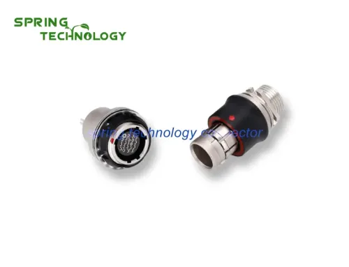
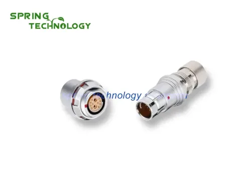
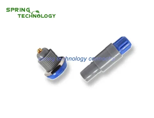
XI’AN Spring Technology Co., Ltd. specializes in producing high-quality single-core or multi-core round push-pull self-locking connectors. 360 ° shielding can provide a full range of EMC protection, perfect resistance to electromagnetic interference.
Xi’an spring technology Co., Ltd. is a professional push pull connector manufacturer integrating connector research and development, production and sales.
Contact me for more info and best price: [email protected], [email protected]
Visit our website: https://www.spring-connectors.com/