

CBTG2BG Push-Pull Connector for Thermal Imaging Cameras 2026: 2B Series 8-Contact 10 A Connector for Infrared Inspection Equipment
The CBTG2BG-SMSM08-D52B is a CBTG2BG push-pull connector for thermal imaging cameras — an 8-contact 2B series connector with 8 low-voltage contacts, a rated current of up to 10 A, a compact construction, maximum contact resistance of 4.8 mΩ, more than 5,000 mating cycles and a durable push-pull locking mechanism. Every specification in this guide is backed by the professional imaging equipment interconnect engineering of Spring Technology.
Pain point: Maintaining a reliable electrical interface on a thermal imaging camera that is carried from inspection point to inspection point — where cables are connected and disconnected constantly, and stable power and signal delivery decide whether a thermal survey is usable?
Core answer: Spring Technology supplies the CBTG2BG-SMSM08-D52B, an 8-contact 2B series connector serving as a CBTG2BG push-pull connector for thermal imaging cameras used in industrial inspection, electrical maintenance, predictive maintenance and condition monitoring. For thermal imaging equipment, connector reliability is important because cameras are frequently moved, repositioned and connected to external power systems, displays, data interfaces or control equipment, and the connector must provide secure locking, repeated mating, electrical reliability and mechanical durability. An industrial infrared thermal imaging camera detects and visualizes temperature differences on electrical cabinets, motors, transformers, industrial machinery, pipelines and building systems, so an interface combining mechanical security with reliable electrical transmission is essential.
1. Technical Parameters & Engineering Standards
This thermal imaging connector is built on the 2B series push-pull platform, used in professional imaging, industrial control and test equipment interfaces.
- Latching Mechanism: Push-pull self-latching system (quick connect without threaded rotation)
- Recommended Hardware: Spring Technology Circular Connector
- Key Metric: 8 low-voltage contacts; 10 A rated current; max. 4.8 mΩ contact resistance; >5,000 mating cycles
| Parameter | Value |
|---|---|
| Connector (this order) | CBTG2BG-SMSM08-D52B — TG plug, 2B shell, key G, 8 contacts |
| Contacts | 8 low-voltage contacts, 0.9 mm contact diameter |
| Rated current | Up to 10 A |
| Wire gauge | AWG 30–22 |
| Contact resistance | Max. 4.8 mΩ |
| Termination | Solder termination, straight cable-mount configuration |
| Housing material | Chrome-plated brass housing, PPS insulator |
| Shielding | 360° EMC shielding |
| Mating cycles | >5,000 mating cycles |
| Shell size | 2B |
| Protection | IP50 (2B series platform, mated) |
| Operating temperature | -45 °C ~ +125 °C (2B series platform) |
| Application | Professional infrared thermal imaging cameras |
2. Thermal Imaging Connector Design Highlights
Inspection equipment works in the field, not on a bench. The design advantages below explain why this CBTG2BG push-pull connector for thermal imaging cameras suits infrared inspection equipment:
2.1 Secure Push-Pull Locking for Field Inspection
- Thermal imaging cameras are frequently carried around industrial sites and operated while the user moves between inspection points. The push-pull self-latching mechanism allows quick connection and disconnection without rotating a threaded coupling, while the locking mechanism helps maintain a secure connection during normal movement and equipment handling — improving connection convenience for handheld thermal cameras during field inspection.
2.2 Eight Contacts for Power and Auxiliary Signals
- Eight low-voltage contacts let a single circular connector accommodate multiple electrical circuits instead of requiring several independent connectors. In a thermal imaging camera, contacts can be allocated to power, control, communication, trigger, synchronization or other auxiliary circuits depending on the system design — useful when designers want a compact external interface that still supports several electrical functions.
2.3 10 A Rated Current
- The connector carries a rated current of up to 10 A with 0.9 mm diameter low-voltage contacts and AWG 30–22 wire support, providing additional electrical capacity for camera power and auxiliary circuits where the application requires it. The allowable current in a finished camera system should still be determined according to the connector configuration, cable, ambient temperature, contact loading and the equipment manufacturer’s electrical design.
2.4 Low Contact Resistance for Reliable Transmission
- The maximum specified contact resistance is 4.8 mΩ, which helps reduce unwanted electrical losses at the connection point — valuable in professional thermal imaging equipment where stable power delivery matters, and where multiple electrical functions share one connector.
2.5 Suitable for Repeated Connection and Disconnection
- Field thermal imaging equipment may connect to different accessories, cables, power sources or test systems throughout its service life. The B series is specified for more than 5,000 mating cycles, making the push-pull connector suitable for applications where repeated mating and unmating are expected.
2.6 Strong Mechanical Construction
- The connector uses a chrome-plated brass housing and PPS insulator. The robust metal construction suits professional equipment that experiences frequent handling, transportation, vibration and mechanical stress, creating a more durable external cable interface than a lightweight consumer-style connector.
2.7 Wide Operating Temperature Capability
- The 2B connector platform specifies an operating temperature range of -45 °C to +125 °C, providing a wide environmental margin for equipment used in industrial inspection environments. The thermal camera’s overall operating temperature must always be evaluated as a complete system, because the connector’s temperature specification does not automatically define the temperature limit of the camera electronics, cable, housing or other components.
2.8 Electromagnetic Compatibility for Sensitive Equipment
- The B series incorporates 360° EMC shielding designed to support electromagnetic compatibility and signal integrity — relevant to infrared thermal imaging systems because professional inspection environments contain motors, variable-frequency drives, power supplies, high-current cables and other sources of electromagnetic interference. A properly designed shielded connector interface helps engineers manage EMI at the equipment boundary.
3. 2B Series Connector Family Overview
The 2B shell is part of Spring Technology’s push-pull self-locking connector family, used in professional imaging, industrial control, test and measurement equipment. The same platform serves this thermal imaging connector and scales across pin counts and contact variants.
3.1 Available Configurations
- Shell: 2B shell size in the push-pull family, with 0B and 1B siblings for smaller layouts.
- Pin counts: 2 to 26 contacts, including the 8-contact configuration in this order.
- Termination: solder termination with straight cable-mount and panel-mount options.
- Materials: chrome-plated brass housings with PPS insulators across the platform.
3.2 Customization Services
- Custom contact allocations and part numbers (such as the CBTG2BG-SMSM08-D52B) matched to each camera’s power and signal plan.
- Pin assignment support for power, control, display, data, trigger and synchronization circuits.
- Shielding and EMC verification for inspection environments.
- Pre-wired camera and accessory harnesses.
4. Applications: Infrared Thermal Imaging Cameras
Thermal inspection depends on an interface that survives daily handling. This CBTG2BG push-pull connector for thermal imaging cameras serves the camera’s external connections.
4.1 External Power and Control Interfaces
Camera power and control signals travel through the 8-contact interface with up to 10 A capacity and 4.8 mΩ maximum contact resistance.
4.2 Display, Monitoring and Data Communication
Display/monitoring interfaces and data communication connections share the same compact connector, with pin allocation matched to the camera architecture.
4.3 Trigger, Synchronization and Auxiliary Equipment
Trigger and synchronization signals plus auxiliary equipment connections use the remaining contacts, reducing the number of separate interfaces on the camera body.
5. Frequently Asked Questions (FAQ)
Conclusion & Call to Action
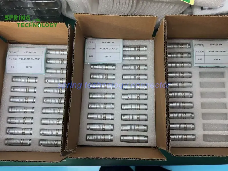
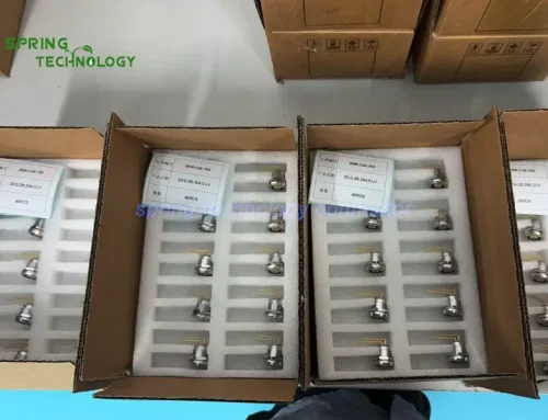
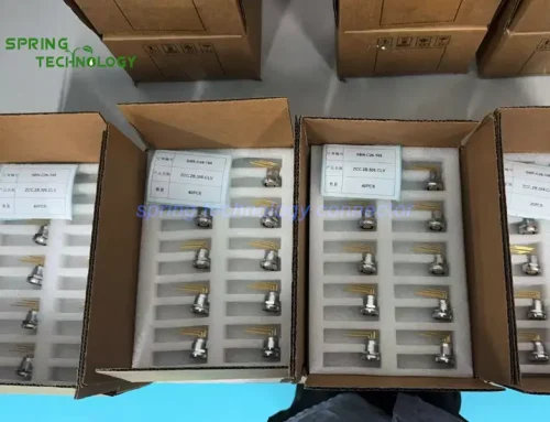
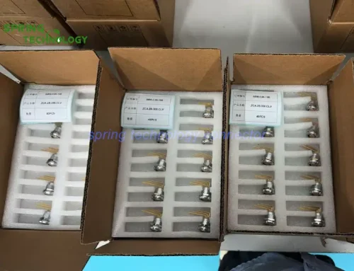
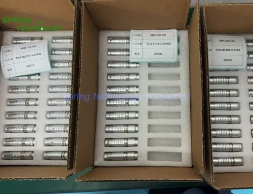
This 2B connector delivery shows how Spring Technology serves infrared inspection equipment — from the 8 contacts and 4.8 mΩ contact resistance of the CBTG2BG-SMSM08-D52B to its chrome-plated brass housing and 360° EMC shielding, every detail was aligned with the customer’s thermal imaging camera requirements. Spring Technology also provides professional customization services for both push-pull connectors and cable assemblies, offering tailored solutions to meet your specific technical requirements.
For more information about our 2B series connectors or to discuss your requirements, contact us at [email protected] or [email protected], or visit our website.
Building a thermal imaging camera or inspection accessory? Send us your power and signal requirements — our engineering team will respond with a tailored CBTG2BG push-pull connector proposal for your thermal imaging cameras within 24 hours.
Further Reading
- CBTG2BG Push-Pull Connector for Crash Test Equipment 2026: 2B Series 4-Contact 15 A Connector for Automotive Crash Test Data Acquisition Systems
- CBTG2BG Push-Pull Connector for Industrial Robot Controllers 2026: 2B Series 19-Pin Connector for Robot Control Cabinets for US Client
- CBTG31FN Push-Pull Connector for Machine Vision Cameras 2026: 31F Series 19-Pin Connector for Industrial Vision and AOI Systems for US Market
- CBTG2FN Push-Pull Connector for Precision Machine Tools 2026: CBTG2FN-SMSM09-D520 and CBZL2FN-SFPM09-S000 for Multi-Channel Miniature Sensor Aggregation for Russian Client
- Push-Pull Connector for Data Acquisition 2026: CBZG0BG-SFSM06, CBZG1BG-SFSM06 and CBZG0BB-SFSM06 for Test, Measurement and Industrial Data Acquisition for Russian Customers
- TGG.2B Push-Pull Self-Locking Connector — Product Page
- 2B Series Connector